Week 8 - Challenge 5 - Core & Cavity Design
AIM
To create the Core and cavity blocks for the switch bezel designed.
Introduction
Core and Cavity
Cavity and core are used in the injection molding process, where the concave part of the mold is the cavity and the convex part is the core.
The cavity and core are used in pairs, with the cavity also referred to as the female mold and the core as the male mold.
These two mold components are the most important parts of a mold.
Parting Surface
Generally, injection mold has two major components: the movable halve and the fixed halve, during injection mouding, these two halves are pressed tightly and form a sealed hollow to avoid the melt flow leakage and maintain certain holding pressure, the pressed surface are called parting surface, usually parting surface are the biggest projection outline of the part.
Design parting surface should follow the following principles:
- Design the injection mold structure as simple as possible. Avoid or reduce side parting as much as possible to reduce the complexity of mold making.
- Ease of de-molding. As far as possible, for instance, the plastic parts should stay in fixed halve of the injection mold and ejected by ejection system, avoid side de-molding action.
- Ensure the dimensional accuracy of the molded parts. Try to make the parts with similar dimensional accuracy requirements in the same module to reduce manufacturing and assembly errors.
- Ensure appearance requirement of the molded parts. Flash or mismatch occurs usually on parting surface, so the parting surface should not be designed on any high quality requirement surfaces.
- Ensure adequate venting. If possible, parting surface should be place at the end of the mold flow. This is going to be a good advantage of filling and venting.
Types of parting surface:
- Flat or straight parting surface
- Stepped parting surface
- Angled parting surface
- Complex or profiled parting surface
Parting line:
A parting line is an area in which the components and parting surface meet or it is a junction between the core half,cavity half and parting surface.
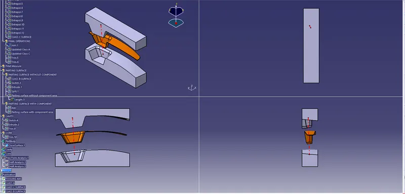
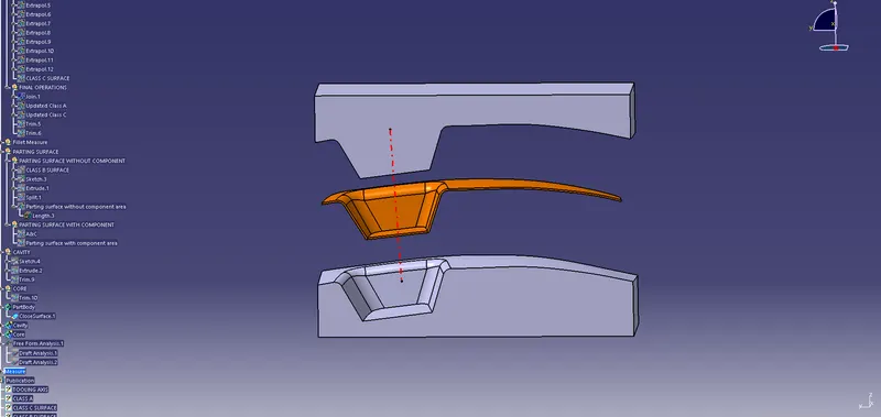
Design of core in step by step explanation in image portion.
Step 1: To cut the improper edges by using create a extrude with a line and split.
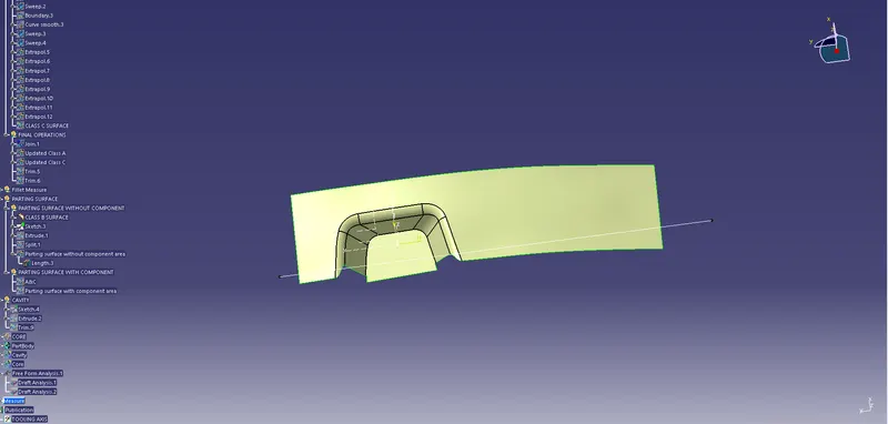
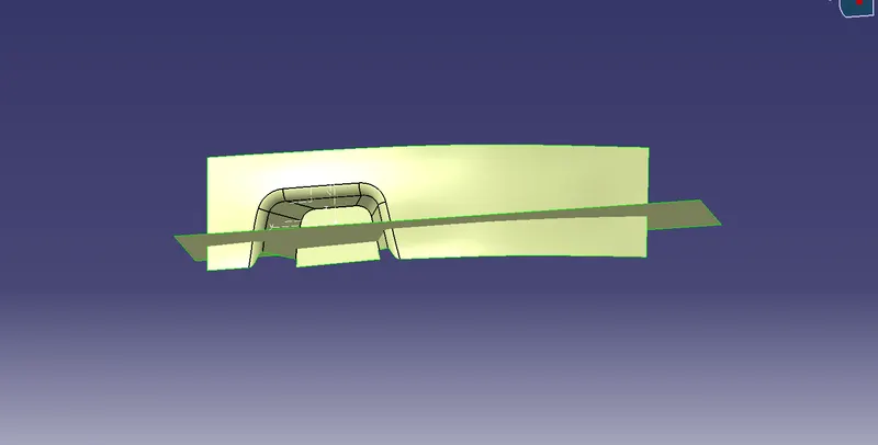
We have a splitting surface between core and cavity i.e., a parting surface which defines where the core and cavity are going to split and the features which come after it.
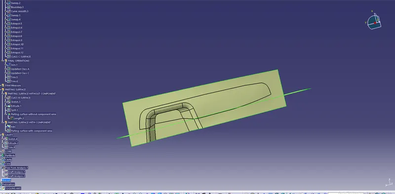
now we are creating a rectangular shape sketch so that can cut off the surface
While creating we also make sure that the boundaries of the sketch are inside the parting surface
CORE BLOCK:
Then, the rectangular sketch is made on the extrapolated surface i.e the parting surface.
This sketch is then extruded along with the normal component and then trimmed with the component to give out the projection feature.
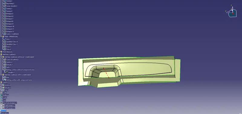
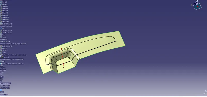
later we trim the core along with the parting surface and extruded surface. The image below shows what a core looks like.
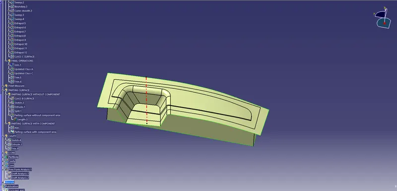
and we will extract the boundary and fill the top to make it a closed surface so that we will get the core solid block out of it.
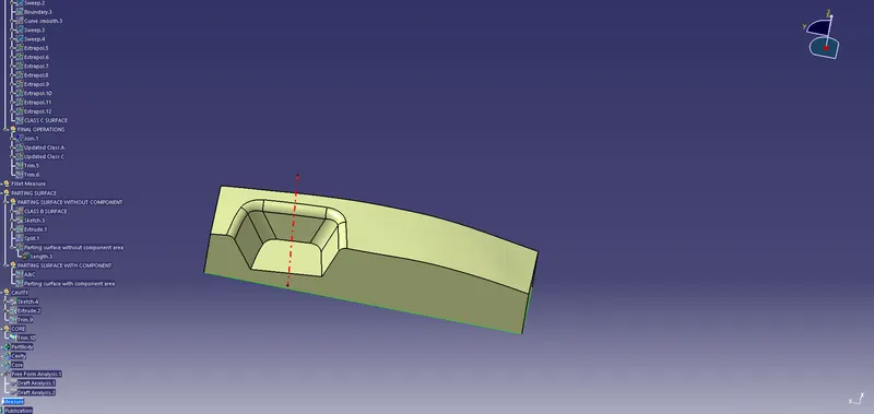
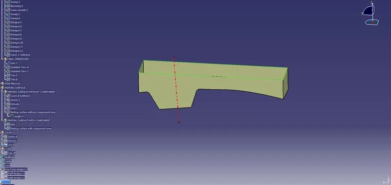
Use the Close Surface feature to make a solid body from the surface.
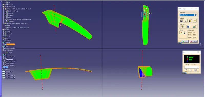
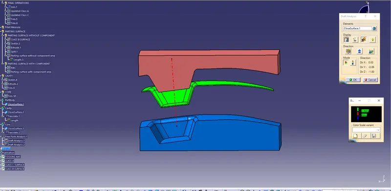
DRAFT ANALYSIS
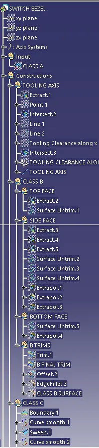
TREE STRUCTURE.

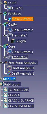
CONCLUSION: The core and cavity for the switch bezel were created and performed draft analysis. Published Tooling axis, Class A, B and C surfaces and part body including parting surfaces.