Week 8 - Challenge 5 - Core & Cavity Design
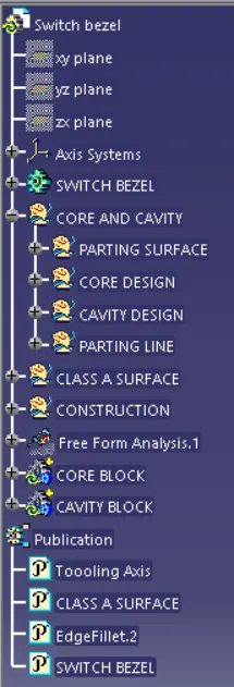
CORE AND CAVITY OF SWITCH BEZEL WITH PARTING SURFACE
To create the core and cavity of the switch bezel, the first step is to create the parting surface with the switch bezel
The parting surface is created by extrapolating the Class A Surface
Then the Class C Surface and Class B Surface are trimmed to get an outline of Class C and B surface to give us the Core inner walls
The inner walls of the core is then created
A position sketch is created on the XY plane and the core box is created with enough gap on all sides of the switch bezel
The rectangular box is then extruded and closed as per given requirements
It is joined and then closed to complete the Core of Switch Bezel
The same steps are repeated for Cavity, but in this case Class B surface and the rectangular box is trimmed to get the bottom walls of the switch bezel
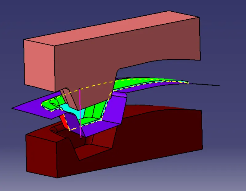
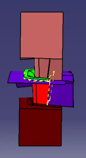
After creating Cavity, an intersect is created to get an idea of the Core, Cavity, Parting surface and Tooling Axis
To get an idea of the Core and Cavity from the switch bezel, translate option is used to move the Core and Cavity on the Z axis
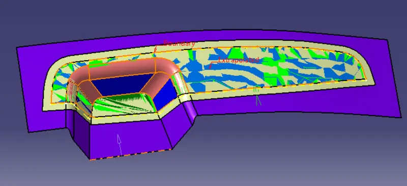
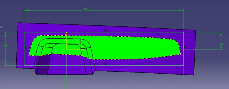
The core and cavity is created by extruding the surface around the extrapolated A surface.
THis is then trimmed along the top side creating the core and the bottom side creating the cavity.
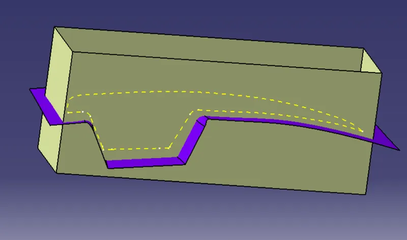
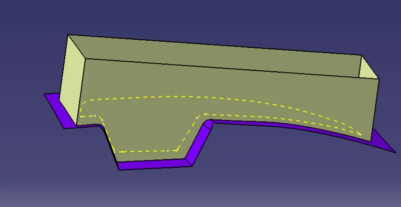
After creating the core and cavity, it is solidified using solid option in part design.
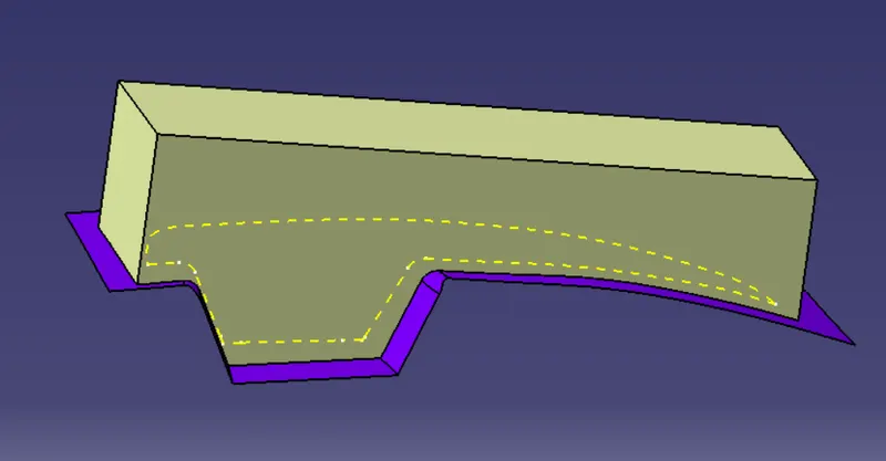
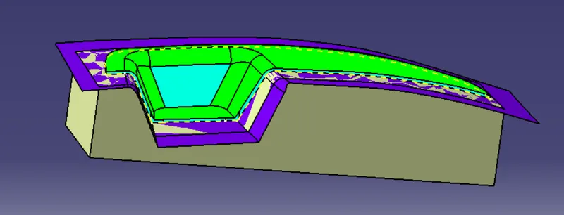
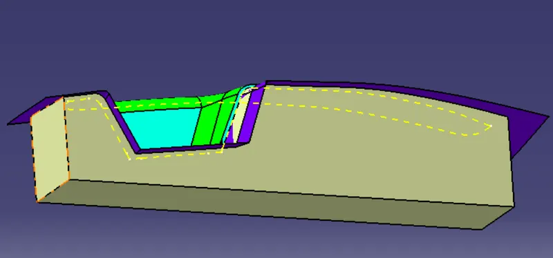
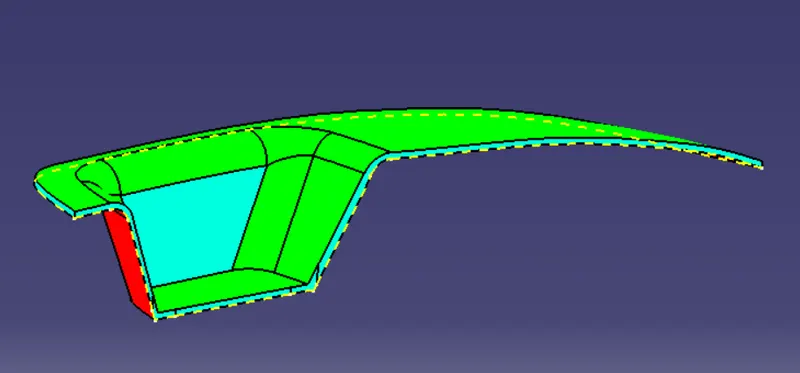
This is the parting surface which is the key component while designing the mold, it allows us to create the required shape at the required size and also act as a refernece.
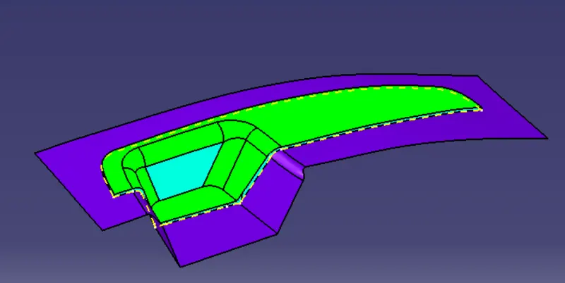
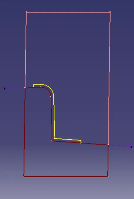
The draft analysis is also done for checking the core and cavity shape.
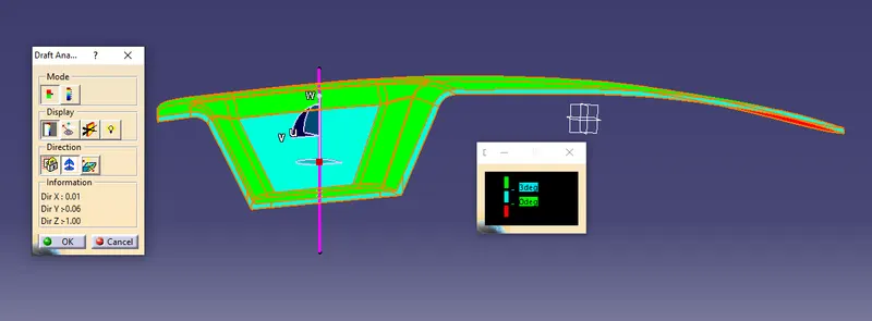
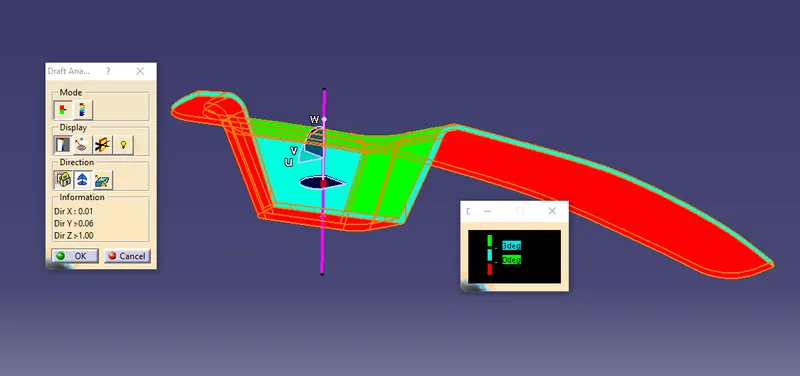
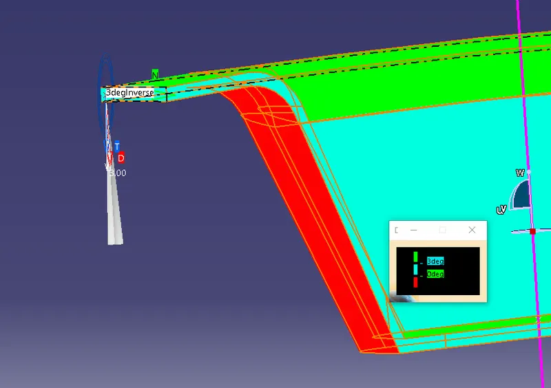
Images of the comleted core and cavity.