Photo Realistic Rendering
Modelling and rendering of American Chopper using Solidworks.
OBJECTIVE:
- To learn how to use Solidworks at an advanced level.
- To equip myself with the adequate knowledge about Designing.
- To model the given project (American Chopper) using various tools available in Solidworks,
- To assemble the designed parts.
- To render the final design using Photoview 360 and Solidworks Visualize.
INTRODUCTION:
This main purpose of this report is to share the knowledge and information I have learnt in Solidworks while creating the Assembly of American Chopper over the past 3 weeks.
Various tools were used throughout the sessions and each tool has its own property. Each tool to be used under various circumstances and there are multiple ways to implement a tool.
DESIGN APPROACH:
The designing approach consists of 3 parts, Namely,
- Part Modelling
- Part Assembly
- Final Rendering
Various parts were designed using Solidworks using the following approach,
- Transmission Belt
- Kick Stand
- Front Fender
- Rear Fender
- Chain
- Oil Tank
- Pedal
- Front Wheel
- Rear Wheel
- Front Fork
- Chassis
- Engine
- Gas Tank
1.TRANSMISSION BELT:
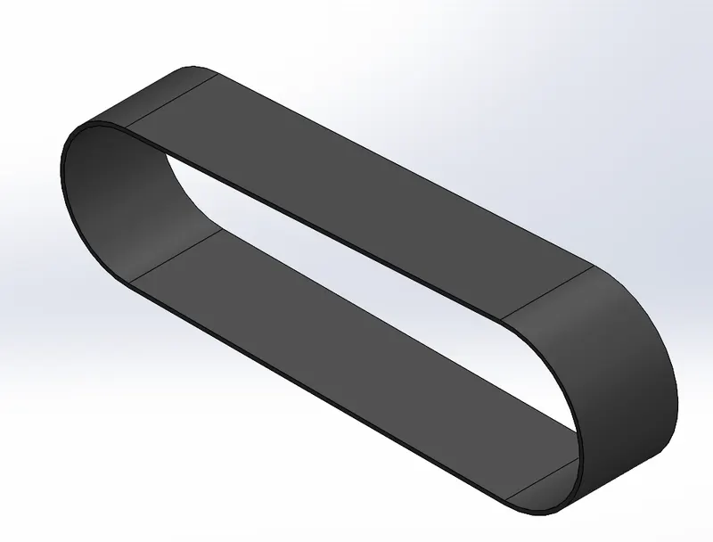
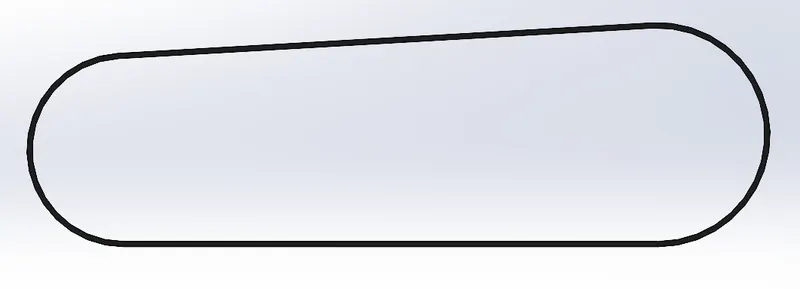
Sketch which is used to draw a sketch to be designed.
Extruded Boss/Base which is used to create a extrusion of the design made so that the desired shape can be achieved.
Fillet which is used to create a round surface at the edge where two surfaces meet.
- The transmission belt is the first part to be modelled which used simple tools such as Sketch, Extruded Boss/Base, and fillet.
- The basic shape was first sketched in the front plane and dimensions were given as per the instructions. Then the sketch was extruded and given an appearance of Matte Rubber.
2.KICK STAND:
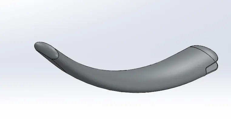
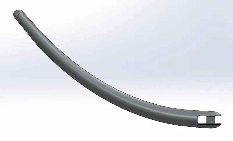
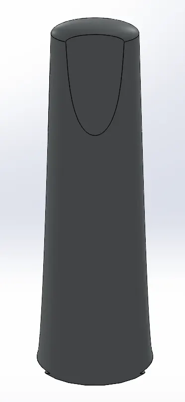
Lofted Boss/Base which is used to create a extrude curves ie a loft.
Dome which is used to create a dome like structre at the desired place
Extruded Cut which is used to cut out desired 3d shapes from any body
- The next part to be designed was the Kick Stand, which uses Tools such as Sketch, Lofted Boss/Base, Dome, Extruded Cut, Extruded Boss/Base and Fillet.
- The basic sketch is first Lofted using the Loft tool which allows us to create the curve like structure for the Kick Stand, then the Dome Feature is applied which allows us to create a Dome at both the ends of the Kick Stand.
- The base part of the Kick stand is cut using Extruded Cut and extra feature are applied using Extruded Boss/Base, Fillet is applied to give it a finished look. Finally, Chromium Plate appearance is applied to the Kick Stand.
3.FRONT FENDER:
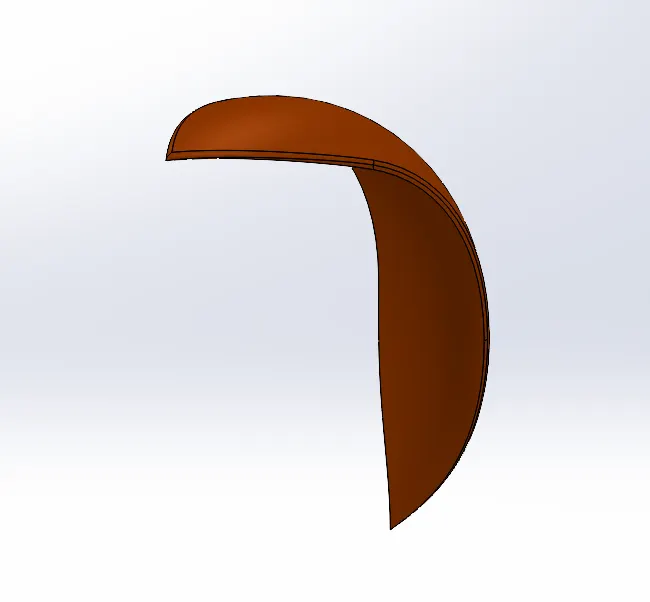
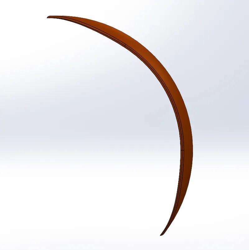
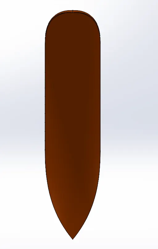
Revolve Boss/Base which is used to create a circular extrusion of the given sketch
Split whcih is used to break the target surface into multiple bodies
- Front Fender is the part over the wheel.
- New features were used such as revolve Boss/Base, Split and Fillet. First the Sketch was drawn and it was revolved using Revolve Boss/Base which gave it a defined shape, then split command was used to give it the v shape as per the diagram. An appearance of Siena was given to the part.
4.REAR FENDER:
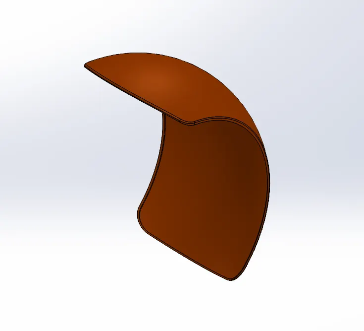
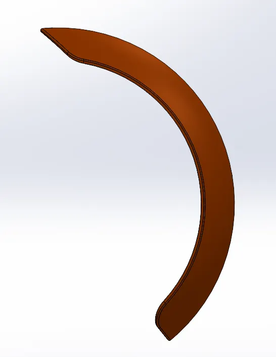
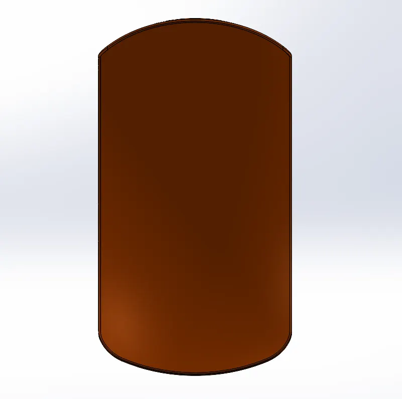
Revolve Boss/Base which is used to create a circular extrusion of the given sketch
Split whcih is used to break the target surface into multiple bodies
- Similar features were used for the Rear Fender as the Front Fender, Revolve Boss/Base, Split, Fillet.
- The Sketch was given using a three-point arc and revolved using Revolve Boss/Base, Split command was used to bring it to the desired shape. Siena was given as the appearance for this Part.
5.CHAIN:
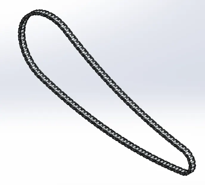
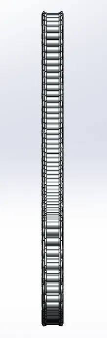
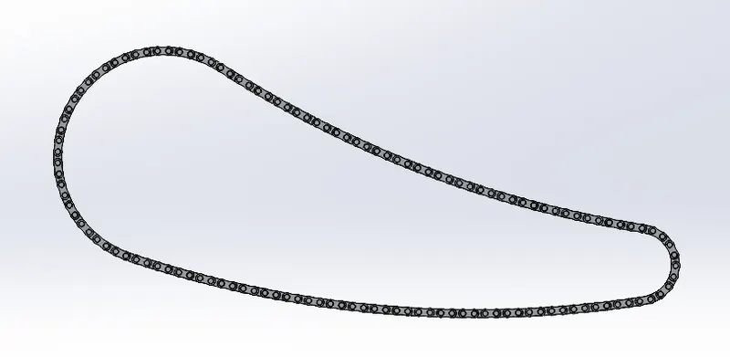
Blocks are used to create parts that are to be used in many parts of the main design, can be saved and used many times
Mirror is used to create a replica of an object/body ie an mirrored object/body
Pattern which is used to create multiple instances of the same part/sketch to save time
- Chain is the part where it allows the transmission of power from the Engine to the Wheel.
- Chain used different Features such as Blocks, Mirror and Pattern. Firstly, each chain links was created using Block feature which created 2 different types links used to create a chain. Now each links was attached and patterned using Linear Pattern and Circular Pattern. Then it was mirrored on the other side. Appearance was given as Chromium Plate.
6.OIL TANK:
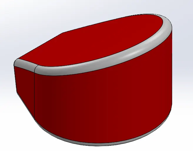
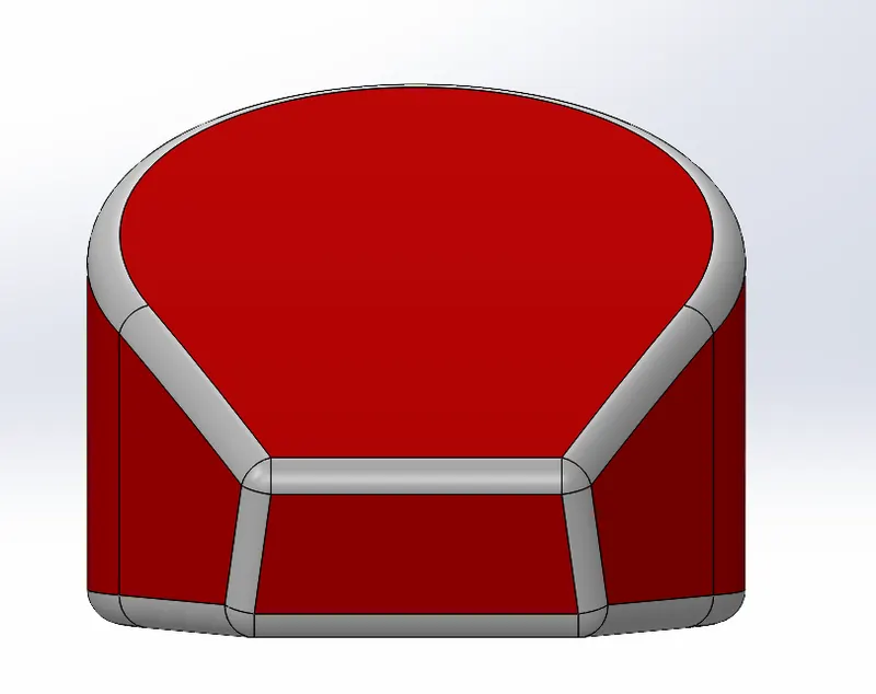
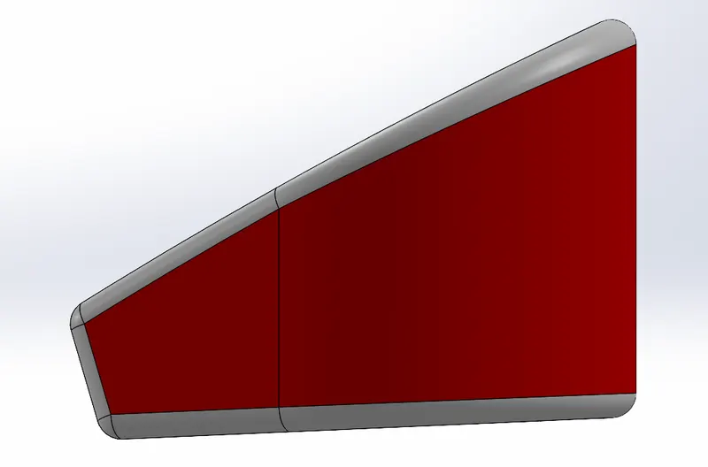
Combine which is used to add two or more bodies or even remove a body from the existing body, to combine bodies
Shell is used to create a cavity inside a created solid body
- New feature was used such as Combine and Shell.
- Oil tank is created using Sketch and Boss Extrude which was again created using another boss extrude and these were combined using the Combine feature which gave us the required shape. Then the Shell feature was used so that the interior of the tank was made empty.
- Other feature such as fillet was used to get the final output, Appearance was given as Candy Apple Red and White as the other parts used above.
7.PEDAL:
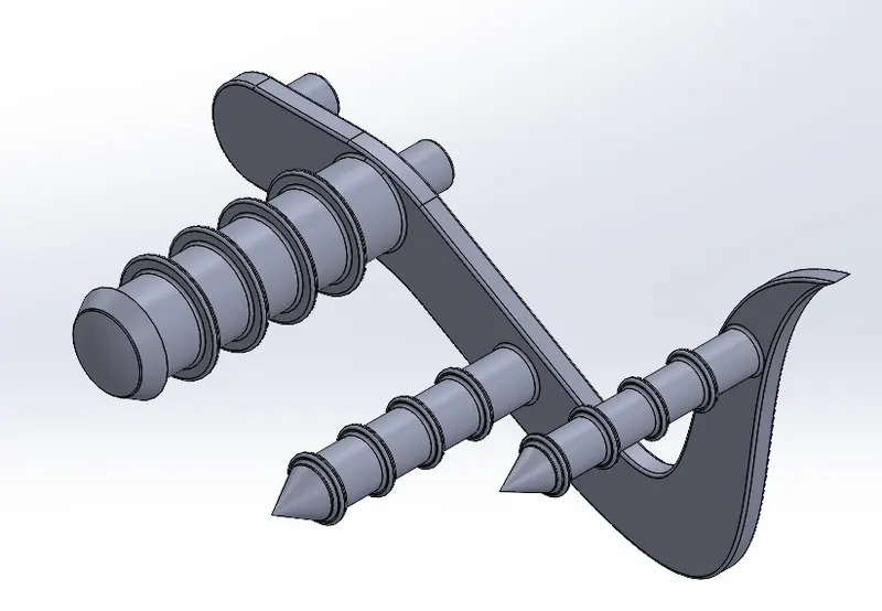
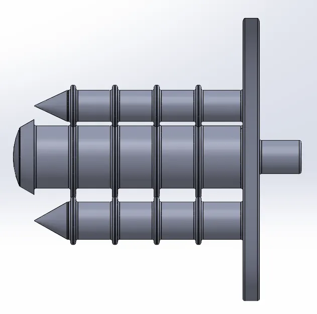
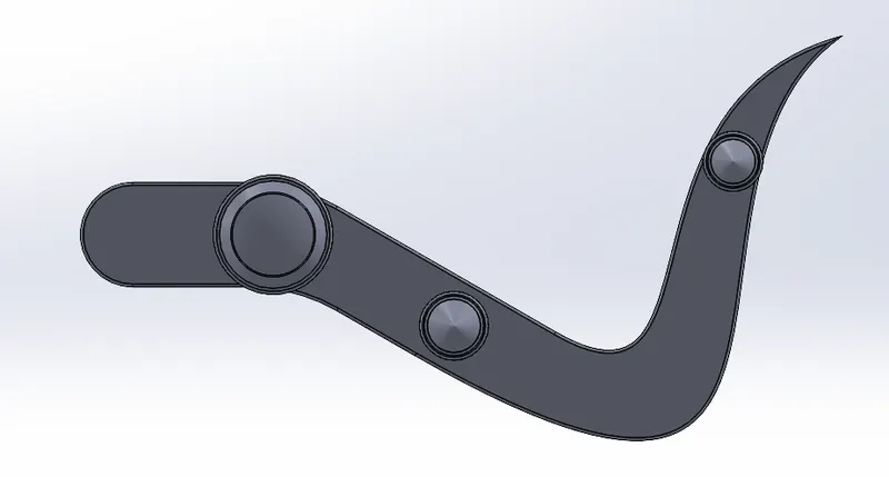
Extruded Boss/Base which is used to create a extrusion of the design made so that the desired shape can be achieved.
Revolve Boss/Base which is used to create a circular extrusion of the given sketch
Linear Pattern which is used to create a pattern but in linear directions
Chamfer is used to create an angle at the edge where two surface meet
Fillet which is used to create a round surface at the edge where two surfaces meet.
- Pedal is the part where the leg rests on both sides.
- Here Pedal uses various features such as Extruded Boss/Base, Revolve Boss/Base, Linear Pattern, Dome, Chamfer and Fillet. First the basic shape of the pedal is sketched which is a tough part to sketch, then it is Extruded using Extruded Boss/Base and other features are also sketched above it and it is also extruded and small revolve parts are also done.
- Now Chamfer option is used which gives an angled view instead of a round view used in Fillet, now Fillets are used to finish it and bring the desired shape, Chromium Plate is used as the appearance.
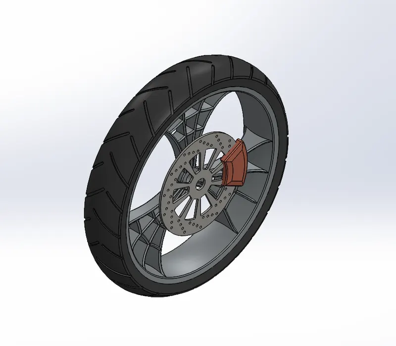
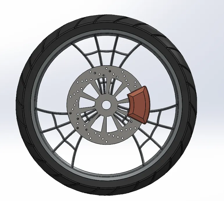
8.FRONT WHEEL:
Revolve it adds or removes material by revloving one or more profiles around a centerline
Fillet Entities allows us to make fillets in an advanced manner
Revolve Cut which is used to make extruded cuts in a revolved shape
Convert Entites allows us to create a sketch from the existing model using the same model as reference
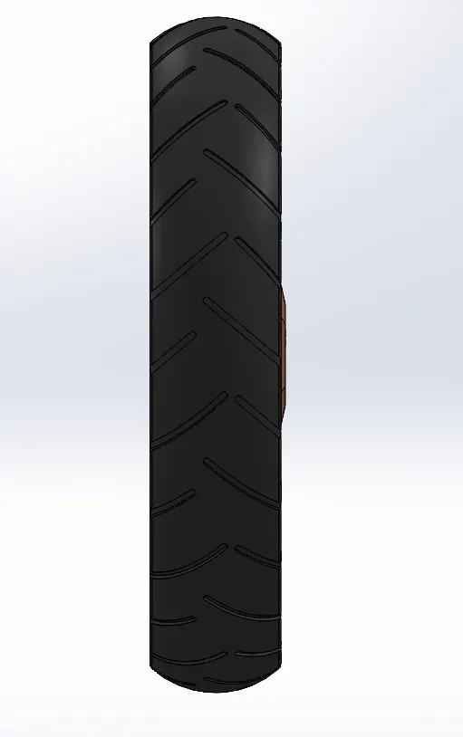
- The Front Wheel is divided into 4 Solid Bodies, Rim, Rotor, Caliper, Tire.
- Features used in this Model are Revolve, Trim, Fillet Entities, Extruded Boss/Base, Revolve Cut, Linear Pattern, Chamfer, Extruded Cut, Circular Pattern and Convert Entities. Usual sketches are designed and Extruded for the Wheel, then the interior parts are designed as per the given instructions, Now the caliper and Rotor is Sketched and other features such as chamfer and fillets are used here to complete Front Wheel.
- The Treads for the tire are also done using Extruded Cuts and circular pattern is applied. Chromium plate is the appearance for the Rim and Glossy Rubber for the Tire and Polished Copper for Caliper, Carbon Steel for Rotor.
9.REAR WHEEL:
Revolve it adds or removes material by revloving one or more profiles around a centerline
Fillet Entities allows us to make fillets in an advanced manner
Revolve Cut which is used to make extruded cuts in a revolved shape
Convert Entites allows us to create a sketch from the existing model using the same model as reference
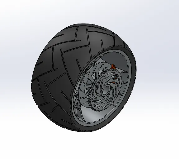
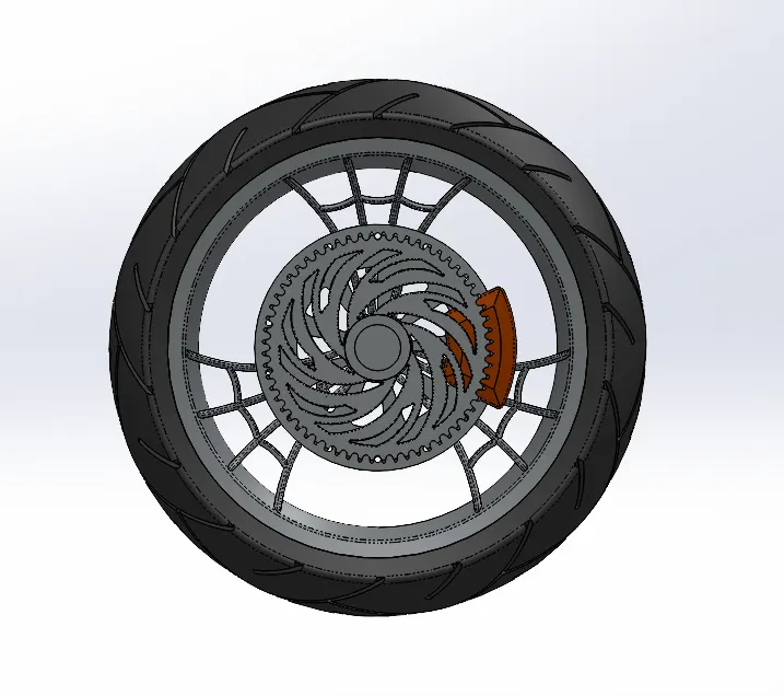
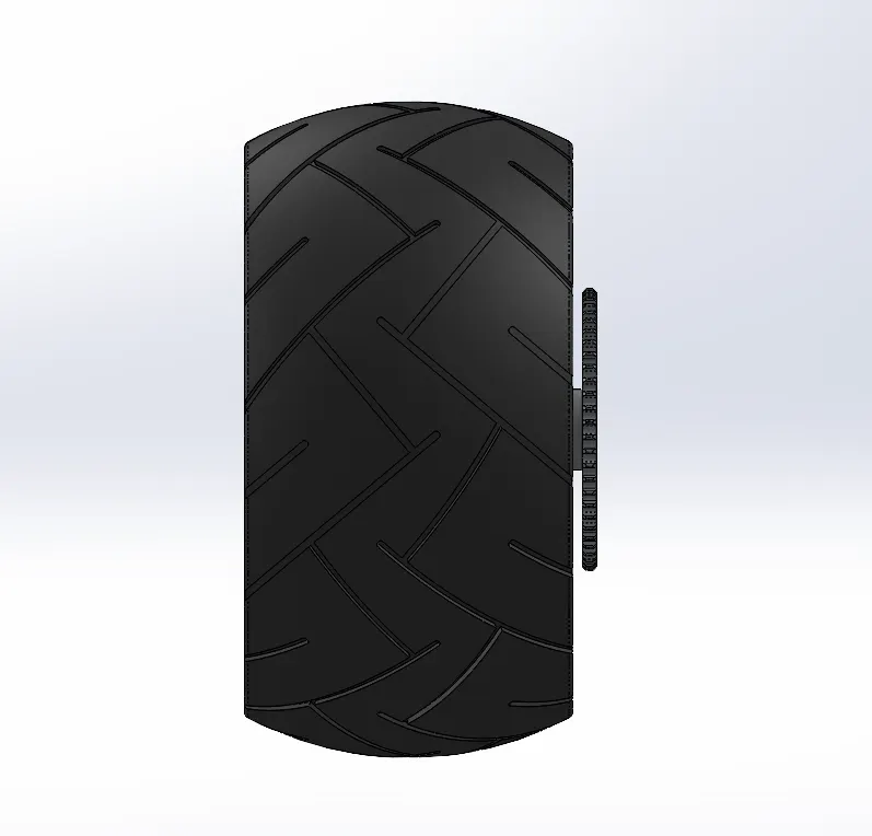
- There are similar parts as the Front Wheel for the Rear Wheel. Extra parts created are the Axle and Sprocket which connects the Chain to the Engine.
- The same procedure is followed as the Front Wheel but dimensions vary as per the Diagram.
- Appearance for the Rim and the Sprocket is Chromium Plate, and the Caliper is Siena, and the tire is Matte Rubber.
10.FRONT FORK:
Move/Copy Body is a similar to mirror but an advanced method which allows us to create copies of bodies along with all the other references
Curve is used to create curves using splines
Sweep creates a base, boss, cut, or surface by moving a profile (section) along a path
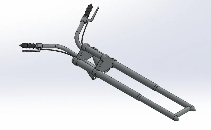
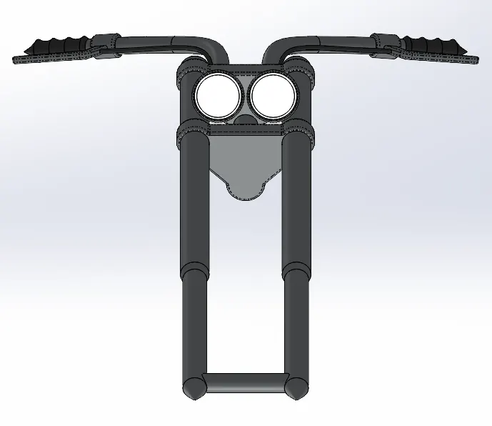
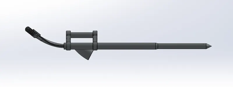
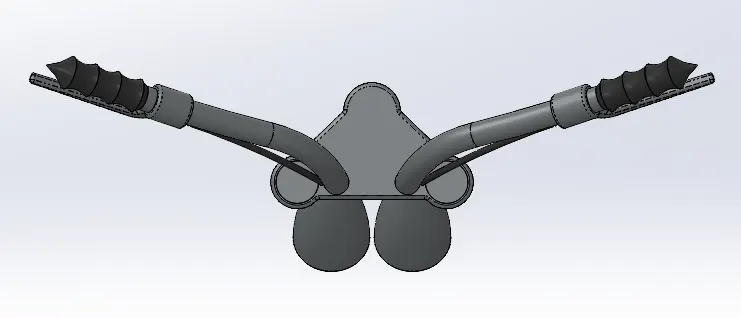
- Front Fork is where the Handle and the front part of the Chopper is situated at.
- New Features used here are Move/Copy Body, Curve and Sweep.
- The basic approach to this design is to create one half of the Front Fork and Mirror it to create the next half, mirroring is done through the Vertical Plane. First the Fork is created using revolve command and then the base is created using extrude which is then patterned. Then the headlights are created using revolve command, additionally the glass inside is created and given a dome command. Now the brake wires are done using the Sweep Command. Finally, Move/Copy Body is done on the other side. Chromium plate is given for the Fork and Glossy rubber is given for the Handle.
11.CHASSIS:
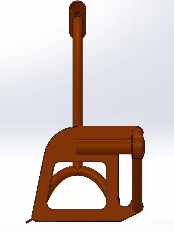
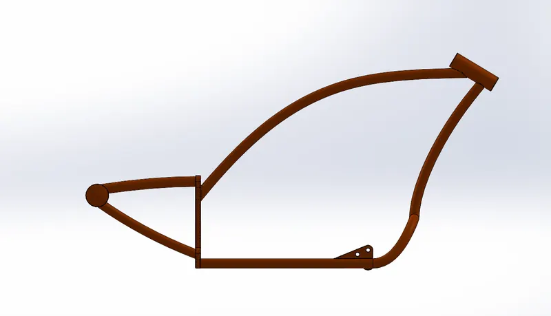
Sketch Picture is used as an reference image in the background for sketching
Project Curve is an option used to create curves along deffernt views of an model
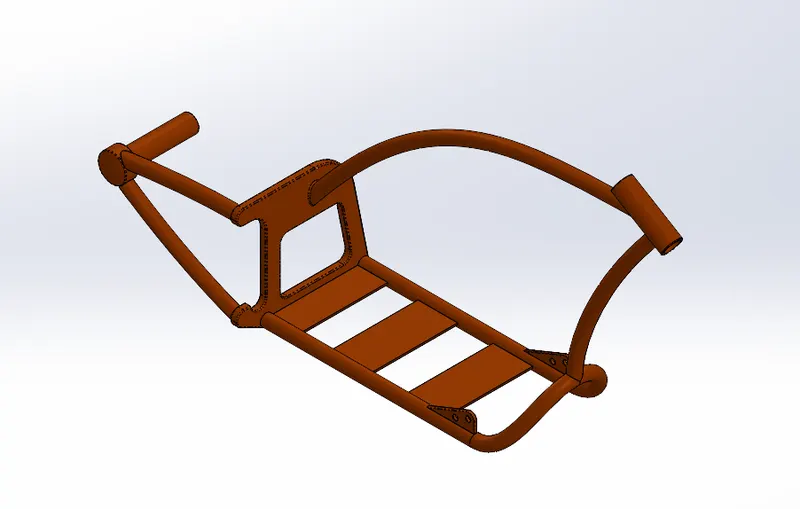
- Chassis is the part where the whole Chopper sits.
- Sketch Picture is used as the base for the Chopper which acts as the base for the drawing, the main features used are Convert Entities, Project Curve, Plane, Sweep, Split, Revolve, Extrude Cut, Combine and Fillet.
- This is the skeleton of the Chopper, so every part is to be designed based on this. Sketches are Drawn and extruded, and other commands are used to complete the Chassis. Appearance is given as Siena.
12.ENGINE:
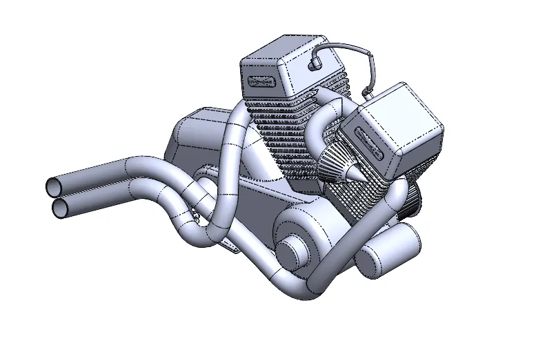
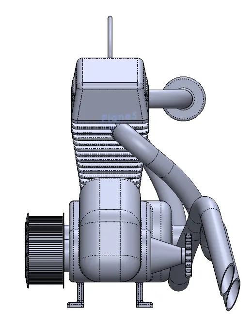
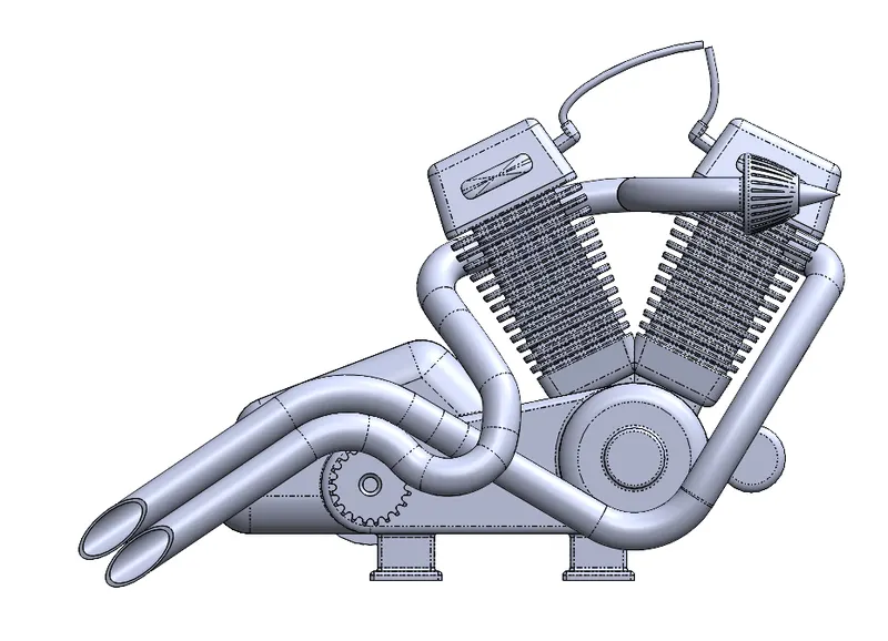
Sketch Picture is used as an reference image in the background for sketching
Project Curve is an option used to create curves along deffernt views of an model
- Engine is the heart of the Chopper and it takes care of the motion of the Chopper.
- Again, Sketch Picture Option is used as the base for the Engine and it gives a good idea on how to design it. Another main part of the Engine is the Exhaust which is to be created using Project Curves, the main function of Project Curves is to create curves based no multiple Planes and axis. Finally, the appearance is given as Chromium Plate.
13.GAS TANK:
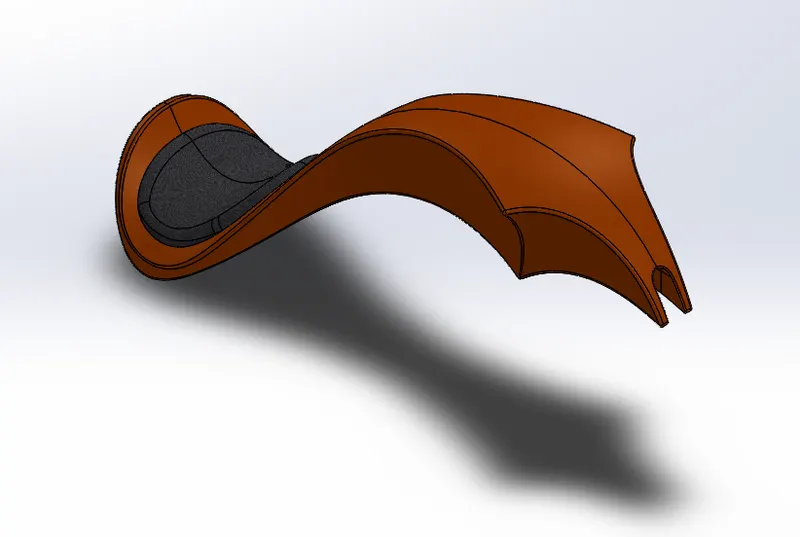
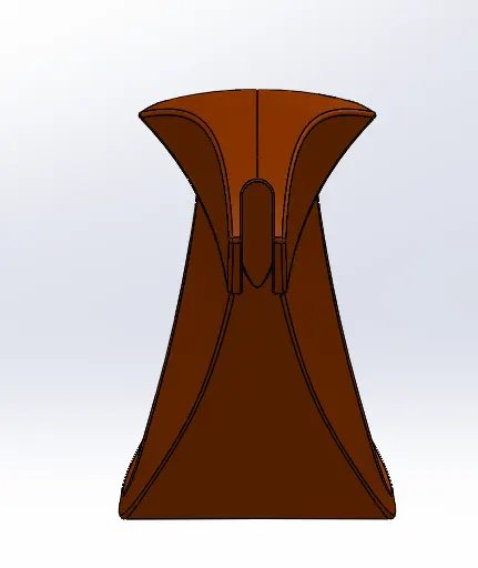
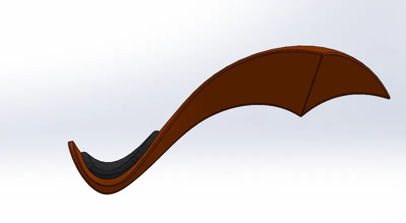
Surfaces are used to create surfaces which cannot be done using extrude, it helps us create complicated curved shapes
- Gas tank comprises of the main design in the Chopper.
- The main Feature used in Gas Tank is Surfaces (Surface Modelling), Where surfaces are created using Projected Curves and then a new surface is added using the Sweep Surface tool which creates a surface along the path created, other Surface tools used are Loft Surface, Fill Surface, Surface trim and Surface Knit.
- Here the First half of the Gas tank is created and then Mirrored. Surface Knit is used to make it as a single body. And at the end Shell Feature is used to create a Hollow space inside the gas tank. The Seat is also created using Surface Extrude.
ASSEMBLY OF CHOPPER:
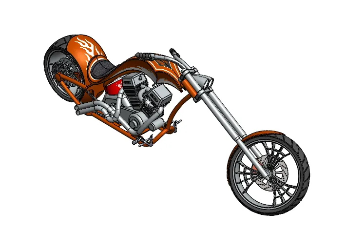
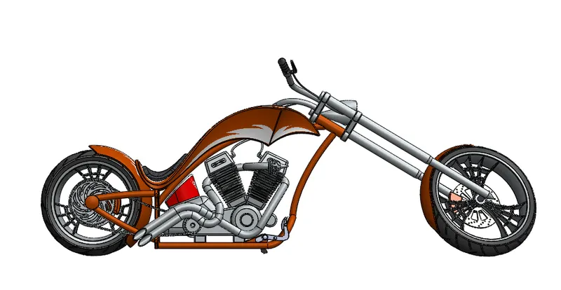
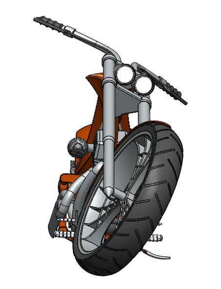
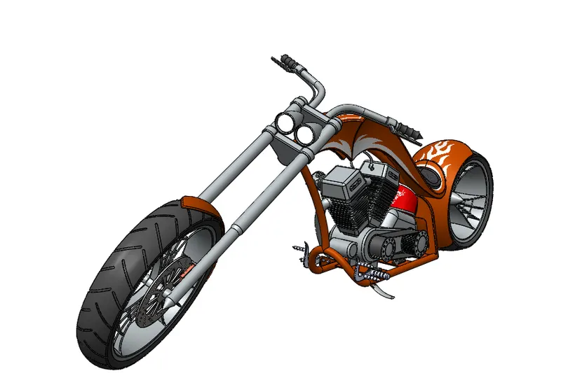
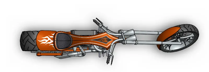
- Assembly is the section where the whole Chopper comes to life as each and every part of the Chopper are assembled together.
- The main features used in Assembling are Mates and Insert Parts. Here insert part allows us to select the part to be inserted for assembling and Mates are used to determine geometric relationships between assembly components.
- Types of Mates used were Coincident, Concentric, Tangent, Angle, and advanced mate such as width Mate and angle Mate.
RENDERING:
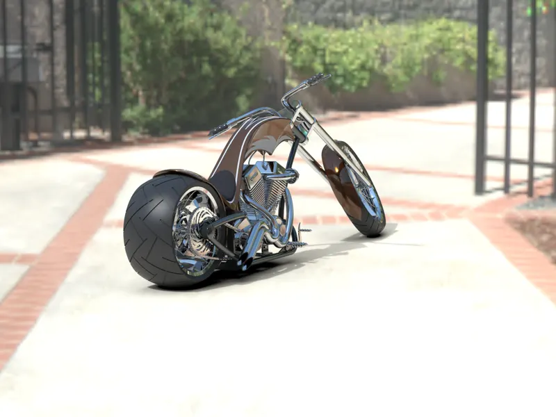
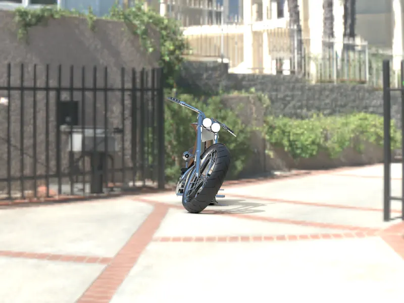
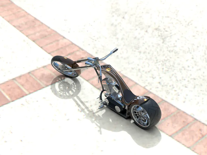
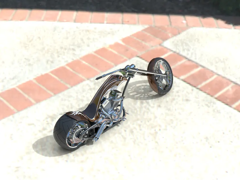
- Rendering is the process of converting 3d image to a real-life image (in terms of looks), which gives it a photorealistic view of the 3d Design.
- The main features used in rendering are Photoview 360 and Solidworks Visualize. Photoview 360 is used to render inside Solidworks whereas Visualize is used to render separately which renders in much more different level and gives a high rendered image.
CONCLUSION
- Various parts of the Chopper were created using Solidworks.
- All of the Parts were assembled inside Solidworks to create the Final Chopper.
- Finally the Rendering was done through Photoview 360 and Solidworks Visualize to create a photorealistic image of the 3d design.