Hood design-Week 2
Designing of Car Hood
OBJECTIVE:
To design a car Hood/Bonnet using Siemens NX Cad as per the NCAP Standards
INTRODUCTION:
Designing the Front hood of a car by using various tools in NX Cad so that we achieve the hood as per the requirements. We will learn how to create a hood from sheet metal and embossing it for the purposes such as the hinge and striker.
We will also learn the trajectory path of a striker and the hinge movement so that the trajectory coincides with it.
NVH (Noise-Vibration-Harshness) is monitored as per our design and will also be implemented.
DATA TO BE USED:
Outer Panel Thickness: 0.75mm
Inner Panel Thickness: 0.75mm
Reinforcement Thickness: 1.5mm
Hemming Thickness: 6mm
Hemming Relief Thickness: 3mm
PROCEDURE:
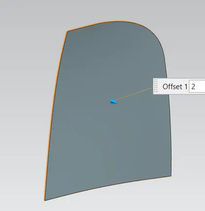
- The given data is downloaded for reference, from which the first step is created, to make a offset for the first Blanking using Offset Surface.
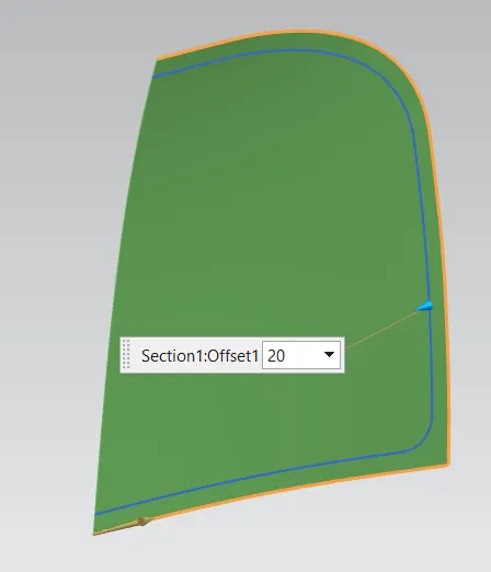
- This is connected using Through curves to make a curve connecting it, whcih is created using a command called Offset in Surface
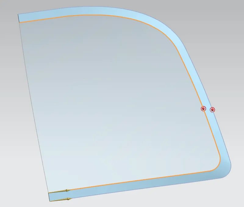
- Again, the process is repeated to create the third and final Blanking and is adjusted as per our requirements.
- The next command used is Law Extension, where the desired side is extended as per the requirement. After this we use Trim and Extend to Cut the extra sheet and make a corner for Convenient usage.
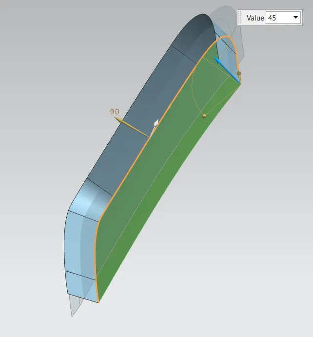
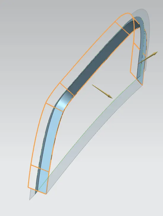
- The next command used is Edge Blend which is used to create fillets to 3d surface.
- Emboss command is used to create an offseted surface for the Mastic to be applied.
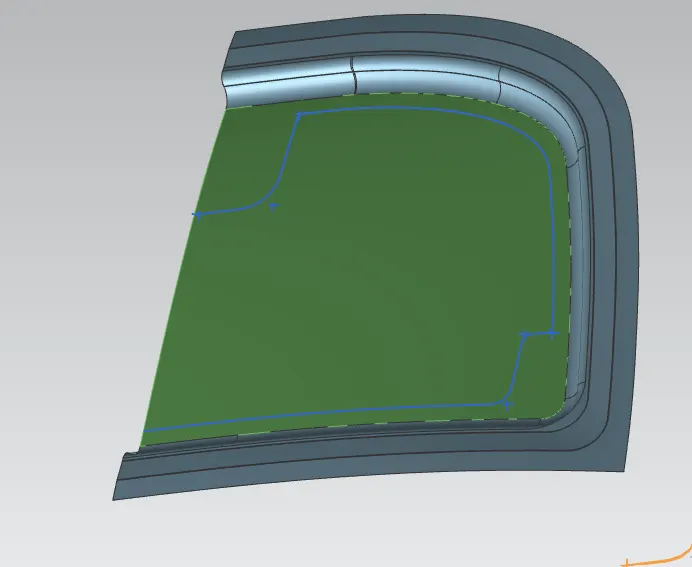
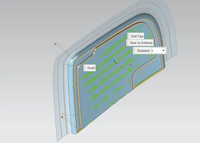
- Separate curves are created on the Embossed Surface for creating new Emboss sufaces.
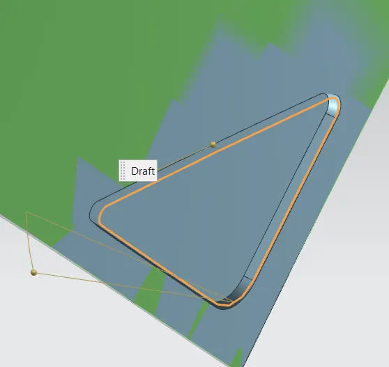
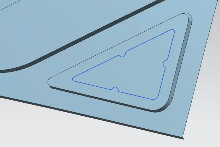
- Trim sheet is used to cut the extra surface to create a new Surface.
- After all the surfaces are created, Mirror Geometry is used to mirror the surface.
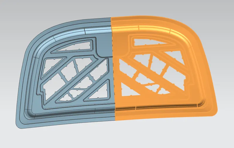
- This is then made as a single piece using Sew Surface.
- Finally, the whole surface is given a thickened value using Thicken Surface.
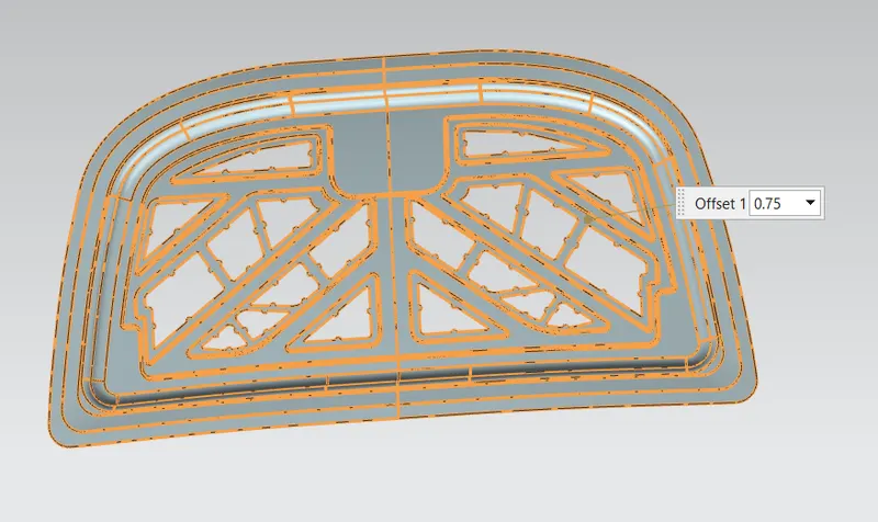
- Next the Outer Panel is created using Offset Surface.
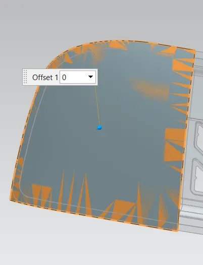
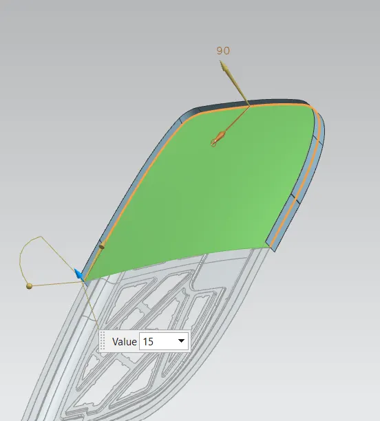
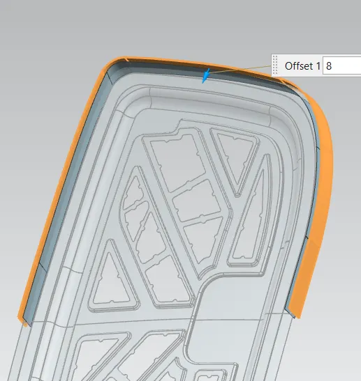
- Now Law Extension is used to create the hemming surface where two Law extensions are created and Face blend option is applied. Here 3 face blend is used to create this option.
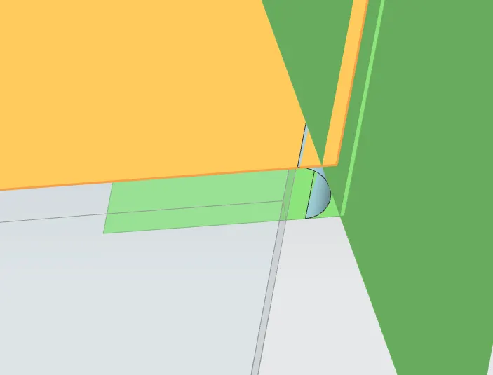
- After Hemming is created, the Hemming relief is created to avoid wrinkles while doing the Hemming process.
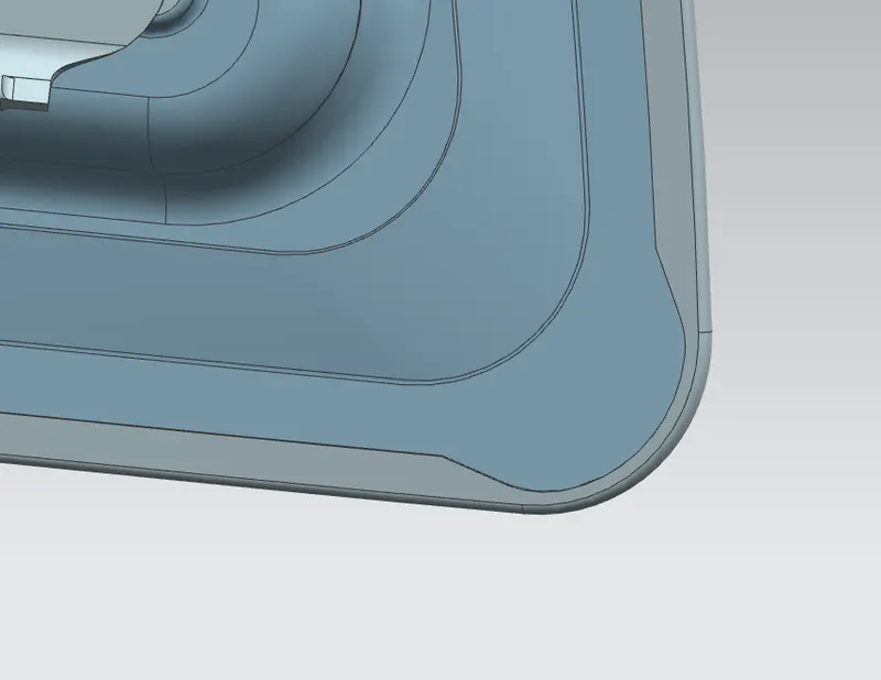
- Now the Panel is separated as Outer and Inner panel using Extracted Body and used for the assembly of the final Hood. It is First Mirrored before Extracting. Then Sewed and then Thickened.
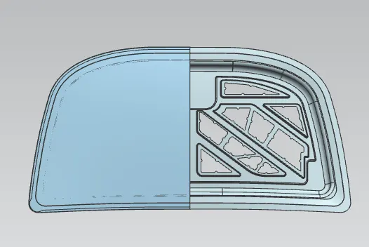
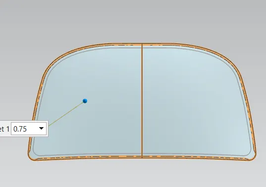
- Now the assembly is created by first importing the panels by using Add Component
- Next the Hinge and Striker is Imported and placed randomly, which is then placed appropriately using Move Components and the Constrained using Assembly Constrains.
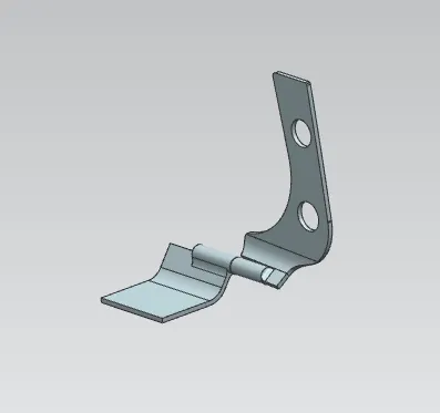
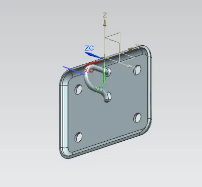
- Now the Hinge is placed used as a reference for creating an Emboss for the Hinge.
- After this is done Emboss is created using the plane reference created using the hinge.
- Now this is mirrored on the other side using Mirror Geometry and Mirror Assembly.
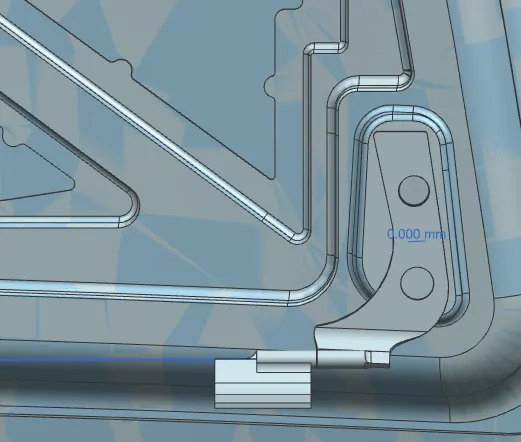
- A common axis is created for both the hinges which is used to create the circle for the
- Now the striker is placed at the required place but not constrained.
- The Circle diameter is created so that the trajectory of the striker path is perpendicular to the path of the circle diameter.
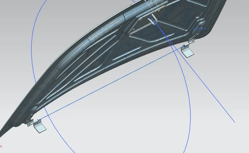
- Now the Emboss is created using a new feature called as Wave Geometry Linker.

- Now finally the Reinforcements are created as per the dimensions.
IMPORTANT THINGS TO NOTE:
- Mastic points to be created at 10mm diameter as it helps in creating a layer for pasting both the layers.
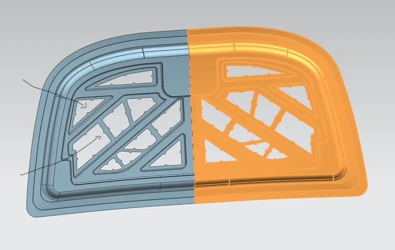
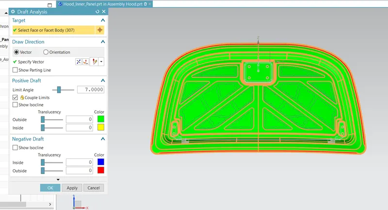
- Emboss angle to be created in such a way that there is no negative draft, avoiding negative draft helps in creating a perfect pressing surface.
- The hemming surface is created as per the dimensions so that a proper hemming is achieved, the important part in hemming is to create a hemming relief in the corners so that wrinkling can be avoided. Here 3mm hemming relief is required.
- While assembling the striker, make sure that the Circle path is perpendicular to the trajectory of the striker, so as to create a circle as the path of movement for the striker.
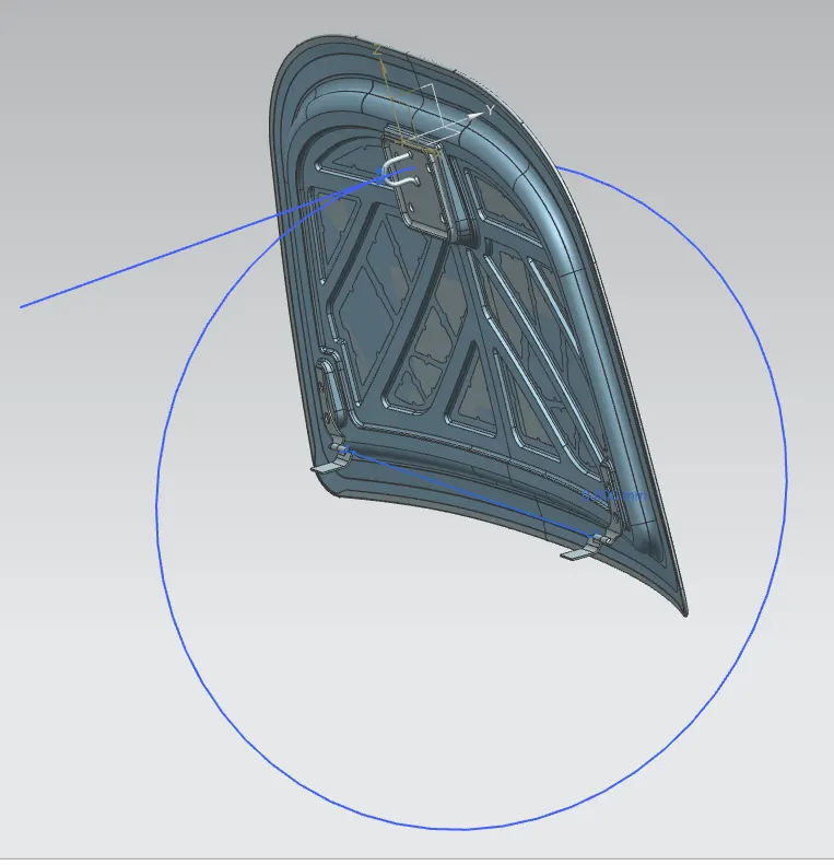
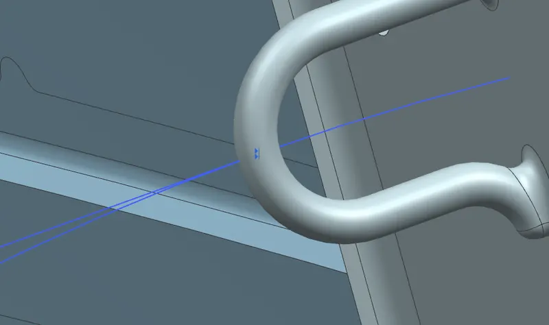
- Finally, the Reinforcements are placed so that the striker and hinge are made much stronger in the assembly.
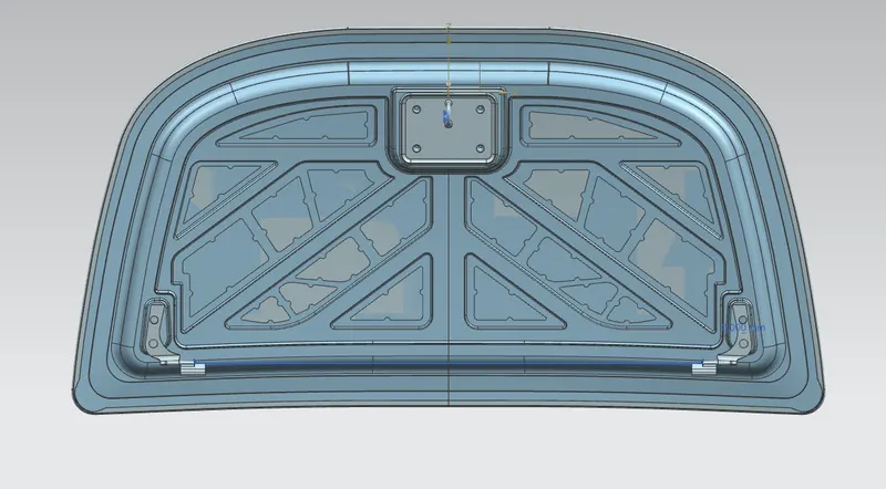
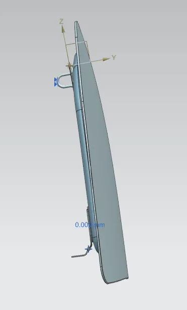
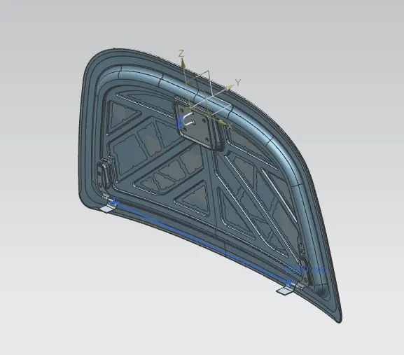
FINAL ASSEMBLY IMAGES:
DRAFT ANALYSIS:
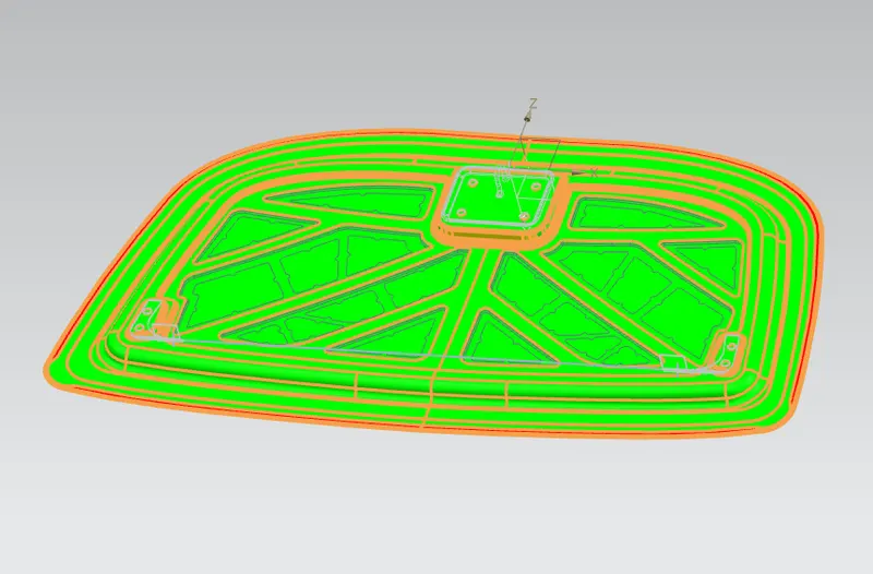
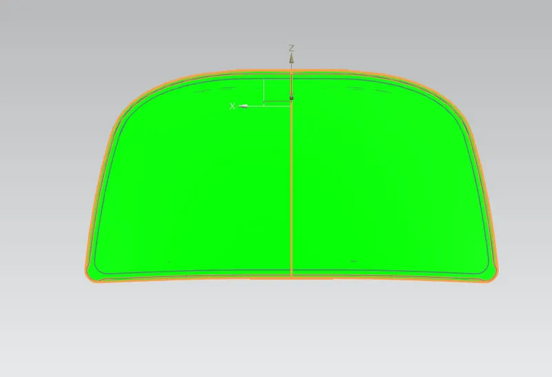
A Draft angle of 7 degrees was applied to check the Draft analysis. Every part appeared to have green areas, few parts were in Blue (Few Emboss Areas) which were corrected later on.
CONCLUSION:
The required Hood designing is achieved in NX cad using the appropriate tools and techniques, the required dimensions are applied. This also satisfies the industry requirements (NCAP).