Radar Mast & Final Assembly of Yacht
YACHT MODELLING AND RENDERING USING SOLIDWORKS
INTRODUCTION
This report is to show the things I’ve learnt over the past 3 weeks in Solidworks Surface and Solid modeling and rendering of a Yacht. I will be explaining the steps and various tools used in creating the solid model.
OBJECTIVE
- To learn more about the CAD software Solidworks
- To equip myself with the necessary knowledge in Surface designing
- To model and assemble the given project (Yacht) using various tools in Solidworks
- To render the complete model with its appropriate environment using Solidworks Visualize.
DESIGN APPROACH
The model was divided into sperate Surface and Solid bodies and later assembled. The parts designed are as follows:
- Propeller
- Radar
- Blue Prints
- Hull
- Garage Door
- Front Seat
- Middle Seat
- Rear Seat
- Superstructure
- Radar Mast
1. Propeller
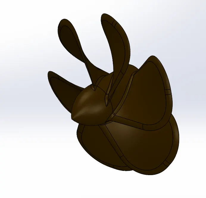
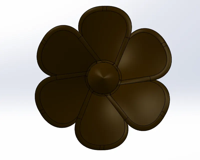
In the process of designing the Propeller, I came across the basic tools that require to sketch and model a part in Solidworks. The basics like commands that were in use for all the parts are:
- Revolve Boss/Base
It is the process where a circular object is created using a line sketch, mostly used to move in circle or central axis.
- Loft Boss/Base
The Loft option was used to give the model a 3D appearance by making transitions between profiles.
Used to give the curved appearance of the propeller
- Pattern
The pattern option is used to give geometric patterns of the used feature or body, to repeat the feature in desired ways is called as pattern.
- Fillet
This feature is used to give a round option for two intersecting sharp edges, to give it a aesthetic purpose of the given object.
2. RADAR
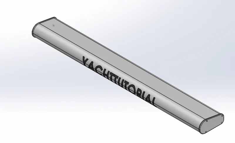
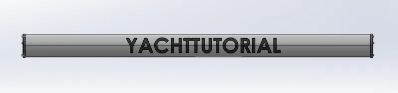
The commands used to create Radar are:
- Sketch
The basic outline of Radar was drawn in a plane in 2D.
- Extruded Boss/Base
This feature allowed us to create an extrude in a curved form with different ends. This helped in creating the basic structure of the Radar
- Extruded Cut
This feature was used to create a cut in the required area without disturbing the main structure.
- Mirror
This option is used to create a mirror image of the given object.
3. BLUE PRINTS
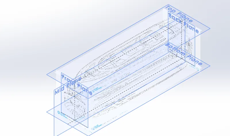
The blue prints were created using the Sketch Picture option In which the sketch pictures are placed in all the views of the required Hull, Front view, Side view, Bottom View, Back View, Top View, and Front View are created in the blue prints.
4. HULL
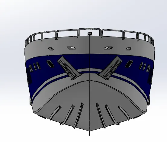
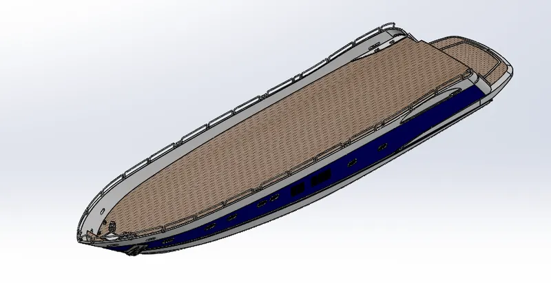
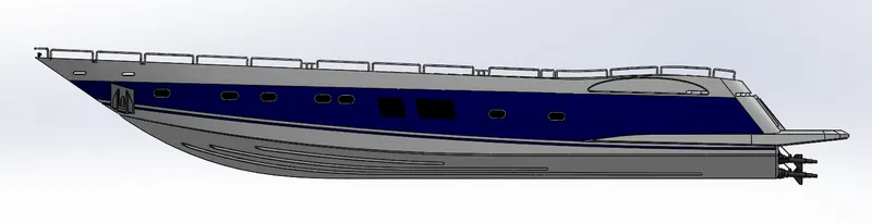
The Hull is created mainly using surface modelling, which includes features to create surfaces using the blueprints different views.
- Surface Extrude
This feature is used as similar to solid extrude where it only extrudes the surface of the given 2D Sketch.
- Surface Loft
This feature is used to create the Loft of surfaces where it creates a shape by making transitions between multiple profiles and guide curves.
- Project Curves
This feature is used to create a 3D curve based on the reference of multiple 2D curves.
- Swept Surface
Swept surface is used to create a sweep along a profile in order to achieve the required shape, it is done by moving a profile along a path.
- Boundary Surface
This feature allows us to create surfaces that can be tangent or curvature continuous in both directions.
- Filled Surfaces
It is used to create a surface with the any number of edges, it creates a surface patch with any number of sides within a boundary.
- Ruled Surface
This feature is used to create a surface from a single edge with required measurements, it extends out in a specified direction.
- Extend Surface
This feature is similar to ruled surface but acts only in one direction.
- Trim Surface
This tool is used to trim surfaces that intersect, which is used to trim the extra surface after intersection.
- Knit Surface
It is used to combine two or more surfaces to make it a single entity so that closed surfaces can be used to create solids.
- Extruded Boss/Base
This feature allowed us to create an extrude in a curved form with different ends. This helped in creating the basic structure of the Radar
- Fillet
This feature is used to give a round option for two intersecting sharp edges, to give it a aesthetic purpose of the given object.
- Save Object
This is used to save a specific object in given project so that it can be used later for other purposes.
- Convert Entities
This feature is used to create a sketch of other objects based on their references; it can create any sketch.
5. GARAGE DOOR
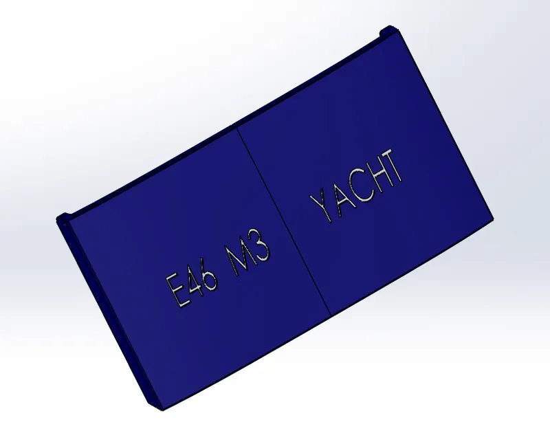
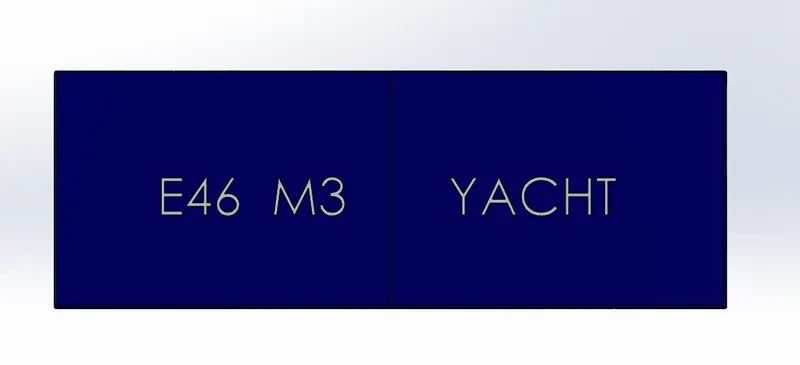
The new features used to create the Garage door were:
- Extruded Cut
This feature was used to create a cut in the required area without disturbing the main structure.
- Mirror
This feature allowed us to mirror the Garage door on the other side to complete the Garage door. This helped in reducing the time needed to create the Garage door.
The Garage door was given an appearance of Blue.
- Text
This feature allows us to create texts in the given object.
- Fillet
This feature is used to give a round option for two intersecting sharp edges, to give it a aesthetic purpose of the given object.
6. FRONT SEAT
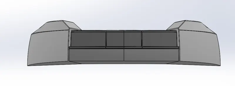
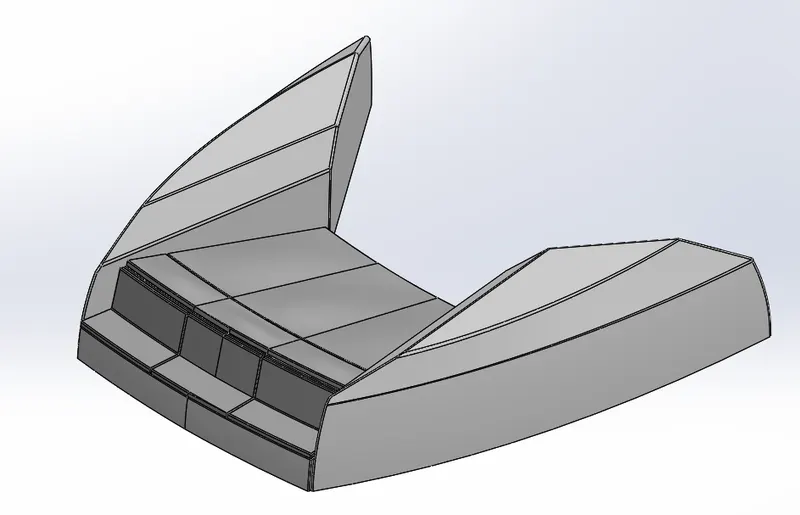
The features used to create the Front Seat were:
- Surface Extrude
This feature is used as similar to solid extrude where it only extrudes the surface of the given 2D Sketch.
- Surface Loft
This feature is used to create the Loft of surfaces where it creates a shape by making transitions between multiple profiles and guide curves.
- Filled Surfaces
It is used to create a surface with the any number of edges, it creates a surface patch with any number of sides within a boundary.
- Ruled Surface
This feature is used to create a surface from a single edge with required measurements, it extends out in a specified direction.
- Extend Surface
This feature is similar to ruled surface but acts only in one direction.
- Trim Surface
This tool is used to trim surfaces that intersect, which is used to trim the extra surface after intersection.
- Knit Surface
It is used to combine two or more surfaces to make it a single entity so that closed surfaces can be used to create solids.
- Extruded Boss/Base
This feature allowed us to create an extrude in a curved form with different ends. This helped in creating the basic structure of the Radar
- Fillet
This feature is used to give a round option for two intersecting sharp edges, to give it a aesthetic purpose of the given object.
- Extruded Cut
This feature was used to create a cut in the required area without disturbing the main structure.
- Offset Surface
This feature is used to create an offset of the surface by a given dimension.
7. MIDDLE SEAT
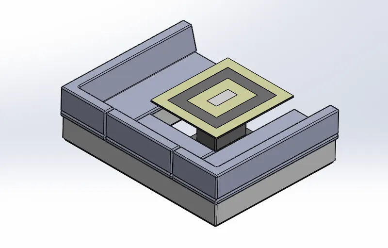
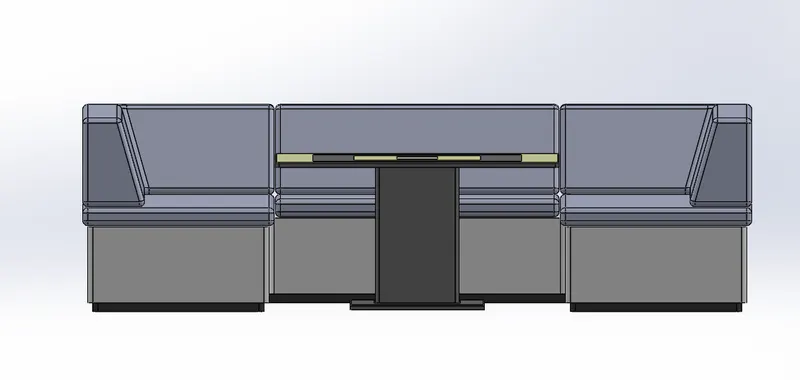
The features used to create the Middle Seat were:
- Surface Extrude
This feature is used as similar to solid extrude where it only extrudes the surface of the given 2D Sketch.
- Surface Loft
This feature is used to create the Loft of surfaces where it creates a shape by making transitions between multiple profiles and guide curves.
- Filled Surfaces
It is used to create a surface with the any number of edges, it creates a surface patch with any number of sides within a boundary.
- Ruled Surface
This feature is used to create a surface from a single edge with required measurements, it extends out in a specified direction.
- Extend Surface
This feature is similar to ruled surface but acts only in one direction.
- Trim Surface
This tool is used to trim surfaces that intersect, which is used to trim the extra surface after intersection.
- Knit Surface
It is used to combine two or more surfaces to make it a single entity so that closed surfaces can be used to create solids.
- Extruded Boss/Base
This feature allowed us to create an extrude in a curved form with different ends. This helped in creating the basic structure of the Radar
- Fillet
This feature is used to give a round option for two intersecting sharp edges, to give it a aesthetic purpose of the given object.
- Extruded Cut
This feature was used to create a cut in the required area without disturbing the main structure.
- Offset Surface
This feature is used to create an offset of the surface by a given dimension.
8. REAR SEAT
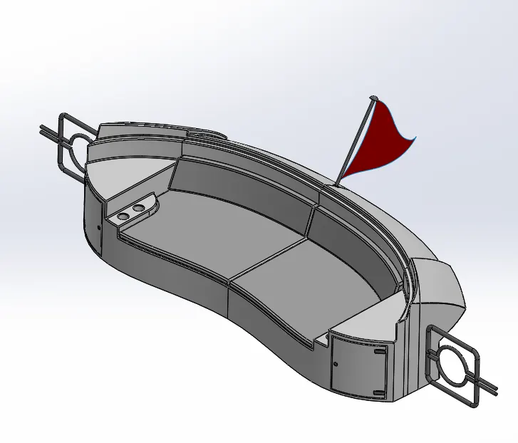
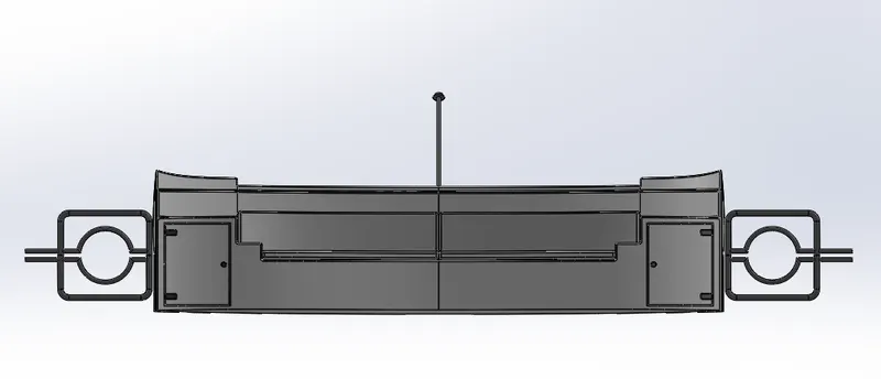
The features used to create the Middle Seat were:
- Surface Extrude
This feature is used as similar to solid extrude where it only extrudes the surface of the given 2D Sketch.
- Surface Loft
This feature is used to create the Loft of surfaces where it creates a shape by making transitions between multiple profiles and guide curves.
- Filled Surfaces
It is used to create a surface with the any number of edges, it creates a surface patch with any number of sides within a boundary.
- Ruled Surface
This feature is used to create a surface from a single edge with required measurements, it extends out in a specified direction.
- Extend Surface
This feature is similar to ruled surface but acts only in one direction.
- Trim Surface
This tool is used to trim surfaces that intersect, which is used to trim the extra surface after intersection.
- Knit Surface
It is used to combine two or more surfaces to make it a single entity so that closed surfaces can be used to create solids.
- Extruded Boss/Base
This feature allowed us to create an extrude in a curved form with different ends. This helped in creating the basic structure of the Radar
- Fillet
This feature is used to give a round option for two intersecting sharp edges, to give it a aesthetic purpose of the given object.
- Extruded Cut
This feature was used to create a cut in the required area without disturbing the main structure.
- Offset Surface
This feature is used to create an offset of the surface by a given dimension.
9. SUPERSTRUCTURE
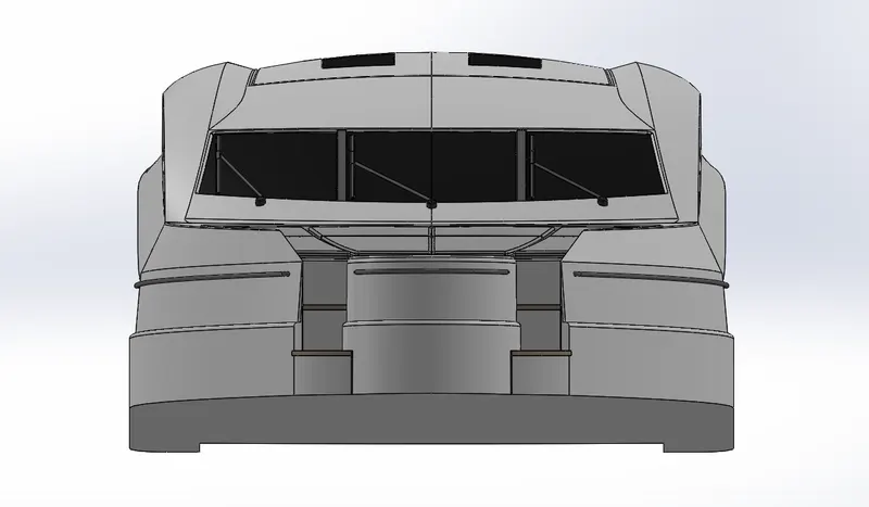
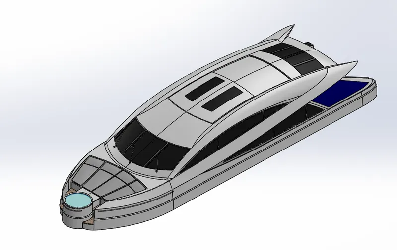
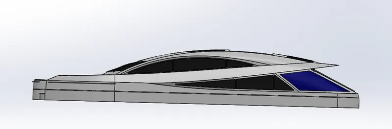
The Superstructure is created mainly using surface modelling, which includes features to create surfaces using the blueprints different views.
- Surface Extrude
This feature is used as similar to solid extrude where it only extrudes the surface of the given 2D Sketch.
- Surface Loft
This feature is used to create the Loft of surfaces where it creates a shape by making transitions between multiple profiles and guide curves.
- Project Curves
This feature is used to create a 3D curve based on the reference of multiple 2D curves.
- Swept Surface
Swept surface is used to create a sweep along a profile in order to achieve the required shape, it is done by moving a profile along a path.
- Boundary Surface
This feature allows us to create surfaces that can be tangent or curvature continuous in both directions.
- Filled Surfaces
It is used to create a surface with the any number of edges, it creates a surface patch with any number of sides within a boundary.
- Ruled Surface
This feature is used to create a surface from a single edge with required measurements, it extends out in a specified direction.
- Extend Surface
This feature is similar to ruled surface but acts only in one direction.
- Trim Surface
This tool is used to trim surfaces that intersect, which is used to trim the extra surface after intersection.
- Knit Surface
It is used to combine two or more surfaces to make it a single entity so that closed surfaces can be used to create solids.
- Extruded Boss/Base
This feature allowed us to create an extrude in a curved form with different ends. This helped in creating the basic structure of the Radar
- Fillet
This feature is used to give a round option for two intersecting sharp edges, to give it a aesthetic purpose of the given object.
- Save Object
This is used to save a specific object in given project so that it can be used later for other purposes.
- Convert Entities
This feature is used to create a sketch of other objects based on their references; it can create any sketch.
10. RADARMAST
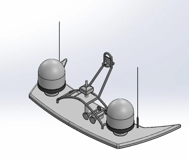
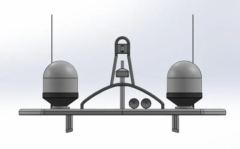
New features used in creating Radar mast are:
- Sketch
The basic outline of Radar was drawn in a plane in 2D.
- Extruded Boss/Base
This feature allowed us to create an extrude in a curved form with different ends. This helped in creating the basic structure of the Radar
- Extruded Cut
This feature was used to create a cut in the required area without disturbing the main structure.
- Mirror
This option is used to create a mirror image of the given object.
- Sweep Boss/Base
This feature Sweeps a closed profile through an open or closed path.
- Convert Entities
This feature is used to create a sketch of other objects based on their references; it can create any sketch.
11. YACHT ASSEMBLY
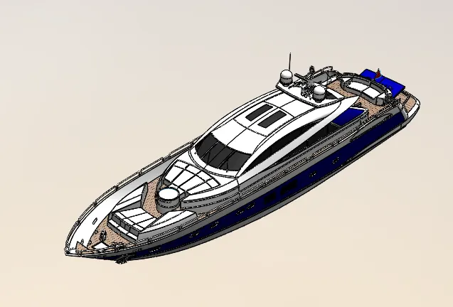
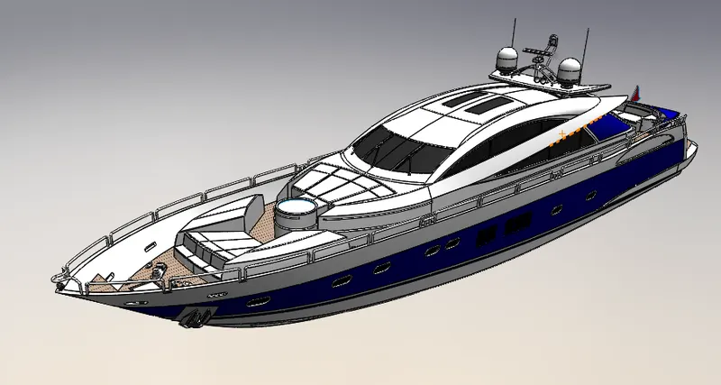
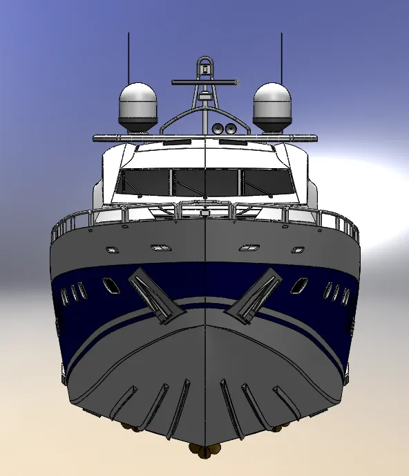
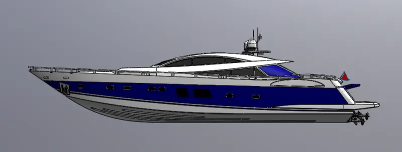
- Assembly
Assembly is a process of bringing together all the parts made using different tools into one file. The assembly of the Yacht consists of 10 parts which were assembled in the assembly option.
- Mates
Mates is the feature where we can fix the parts in the desired location based on the assembly. There are different kinds of mates used like coincident, tangent, concentric, angle and some advanced mates such as width mates, angle mates. These mates have specific purpose and can be used according to the model’s requirement.
RENDERING
Rendering was done using photoview 360 as the initial stage in which the basic lighting was given and then final rendering was done using Visualize where background scene was given and the lighting and shadows were adjusted accordingly.
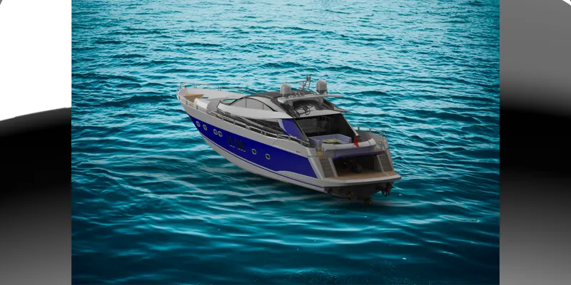
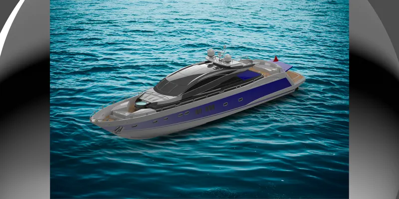
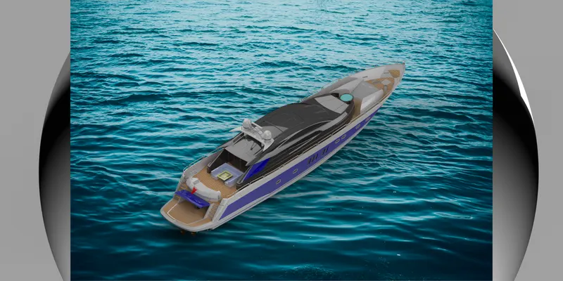
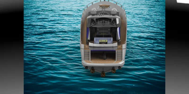
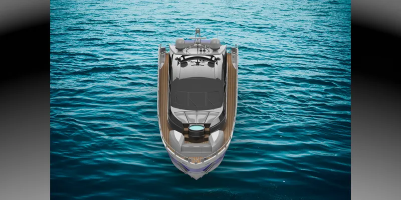
(Note : Rendering done as per the system capability, only basic rendering could be done)