Week 8 - Challenge 5 - Core & Cavity Design
CORE AND CAVITY DESIGN OF
SWITCH BEZEL
Draft is the angle that is put on the side faces of the part so that the part doesn’t get trapped in the mold or cast. Here the draft angle is checked on switch bezel in CATIA V 5.
THE CLASS A SURFACE IS PROVIDED TO US.
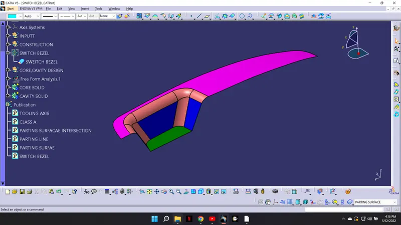
TOOLING AXIS YZ PLANE DIRECTION.
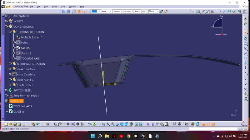
Next bisect both the lines and obtain the line that is going in the direction of the dummy tooling axis. That will be the tooling axis in the yz direction.
INTRESECT AT XZ PLANE.
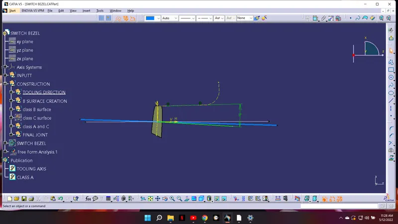
Take the intersect of the switch bezel and the XZ plane. Identify the faces which are parallel to the dummy tooling axis. Since there is only one face which will create a problem in the removal of the component. We will sketch another line which is at an angle to the surface.
MAIN TOOLING AXIS.
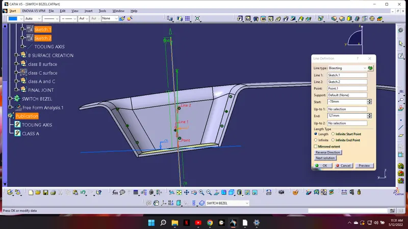
Now we have got tooling axis in the xz and yz direction. Bisect both the lines and obtain the line which is in the direction of the dummy tooling axis. That is the required tooling axis of the switch bezel.
DRAFT ANALYSIS CLASS A
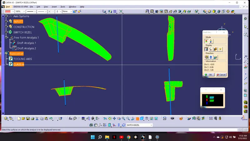
In the tool bar then insert analysis next take the compass and put it over the tooling axis to get the required direction of draft analysis and then lock the draft direction.
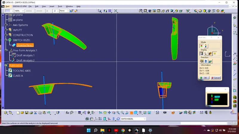
Then double click on the component and it will show the draft analysis. It is shown according to different colors different draft angle.
DRAFT ANALYSIS FOR FINAL SOLID.
CORE AND CAVITY DESIGN.
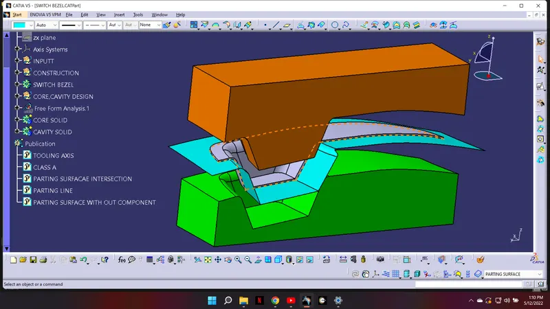
The mold core & cavity are the shaped section in either half of the mold tool which give the plastic product its final shape. The hot molten material is injected into the core, cavity and then sets hard into shape. The design of mold is essential in the correct formation of the product.
CORE DESIGN
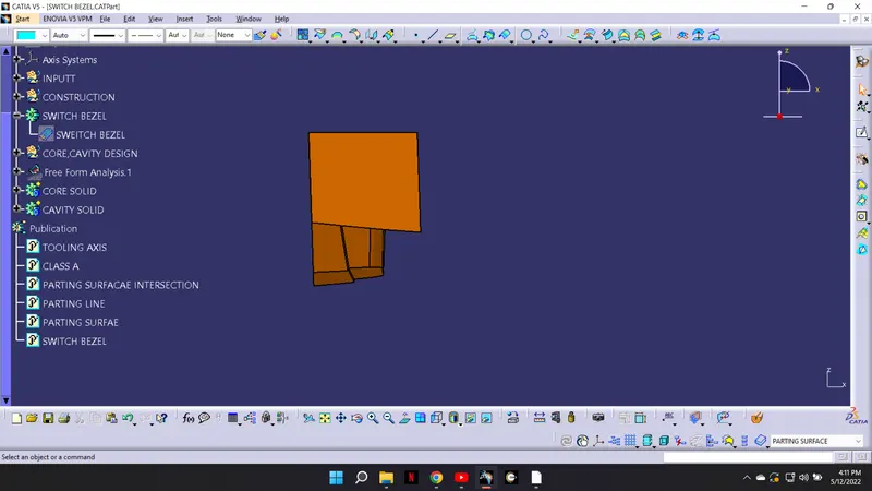
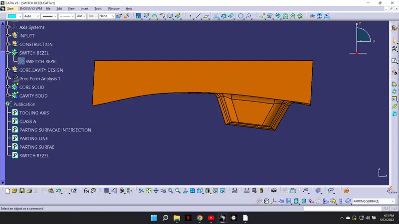
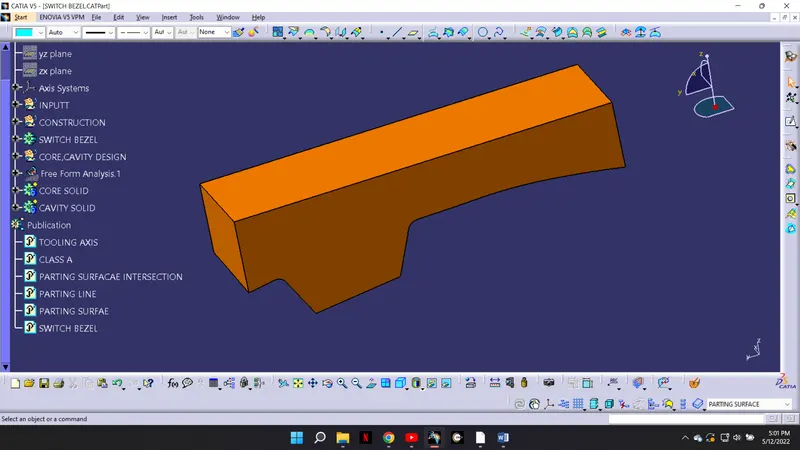
Extrude the rectangle in the direction of the tooling exist and trim the lower part and the parting surface to get the required shape and close the surface to make it solid.
CAVITY DESTGN
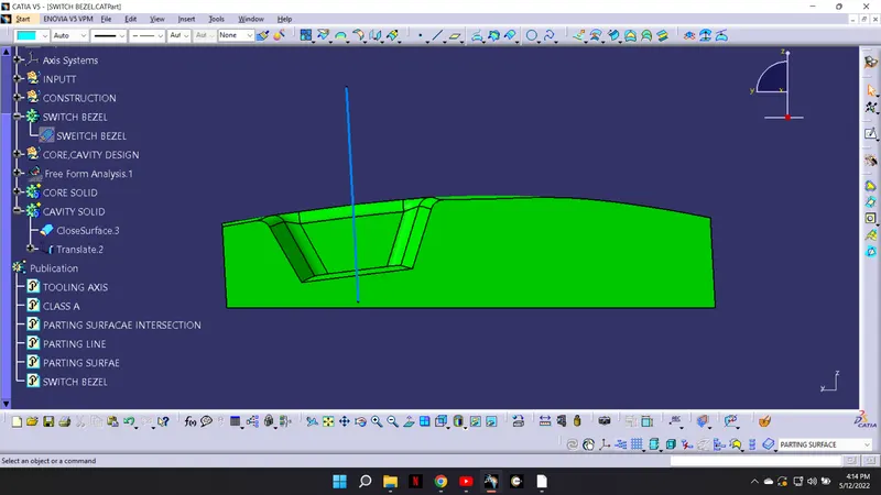
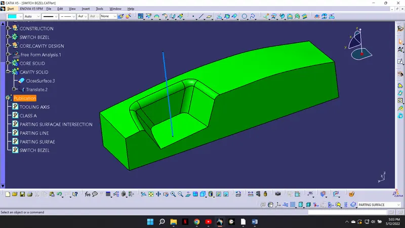
For cavity design take the parting surface and extrude the rectangle in the direction of the tooling axis. Trim the rectangle shape and the parting surface get the required shape.
PLARTING LINE.
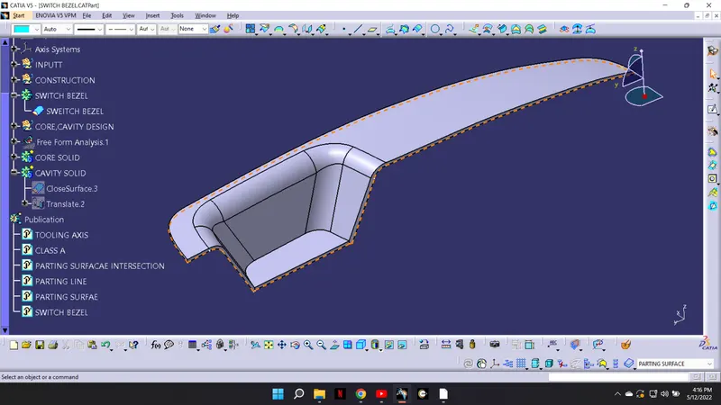
A parting line is line of separation on the plastic part where the two halves of the plastic infection mold meet. The line actually indicates the parting plane that passes through the part.
PARTING SURFACE.
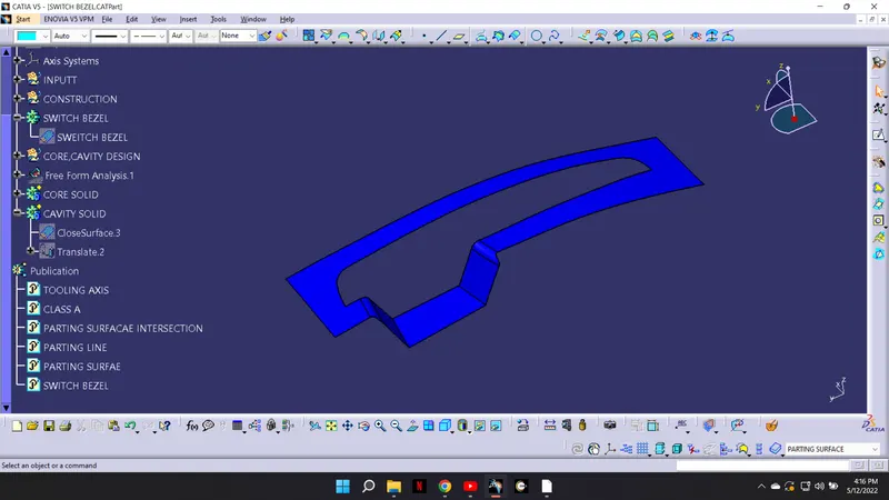
The parting surface of a mold are those surfaces of both mold plates adjacent to the impression which butt together to form a seal and prevent the loss of plastic material from the impression.
FINAL OUTPUT