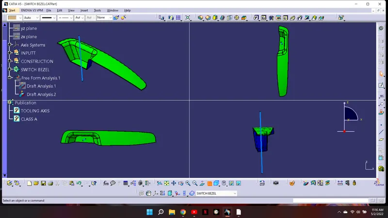
Week 8 - Challenge 3 - Switch Bezel Design
CREATION OF TOOLING AXIS DIRECTION ON BISECTIING METHOD
ON the identification the normal axis has been taken for the flat surface as a tooling surface
USING OF BISECTING METHOD
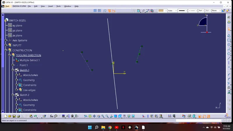
SKETCH 2 HAS CREATEAD AXIS USE OF BISECTING LINE
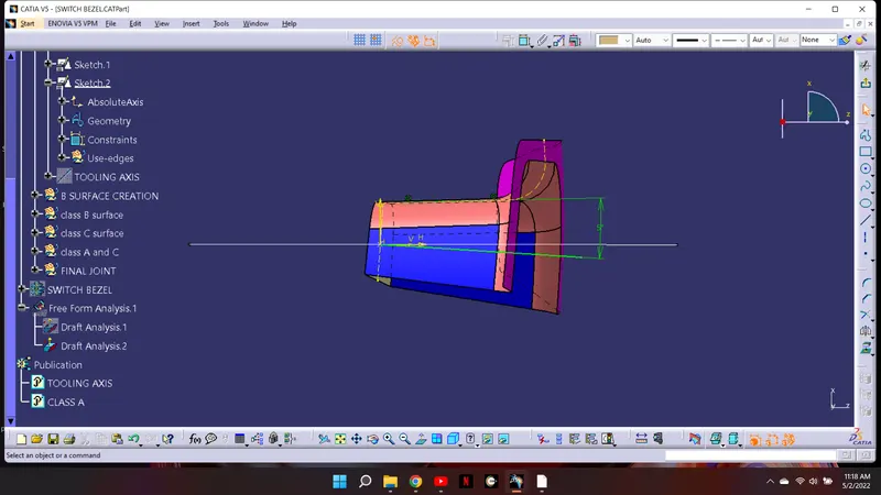
The first initial method we have taken YZ to create the side wall face of the bezel the edges of the switches has been projected and bisecting lines has been created clearing both the wall
Then to that considering the XZ plane and taken reference form one surface and line has been created based on the point and angle with reference to the projected line the angle has been taken has 6 degree
ON BISECTING BOTH THE LINES WE GOT THE LINES WE GOT THE EXACT TOOLING DIRECTION THAT CLEARS ALL THE DRAFT ANALYSIS
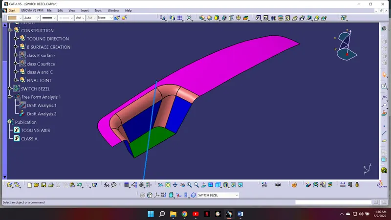
CREATION OF CLASS B SURFACE
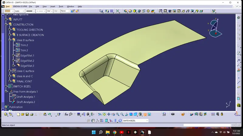
CREATED CLASS C SURFACE
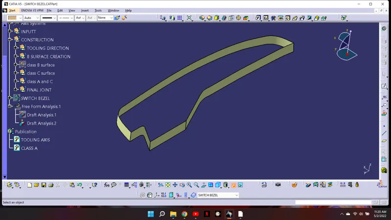
FIFNAL TRIM IS CREATED WITH CLASS A , CLASS C HAS BEEN JOIN
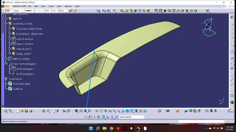
FINAL TRIM IS CONVER INTO COLSE SURFACE SOLID BODY USING CLOSE SURFACE
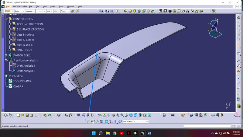
DRAFT ANALYSIS CLASS A SURFACE
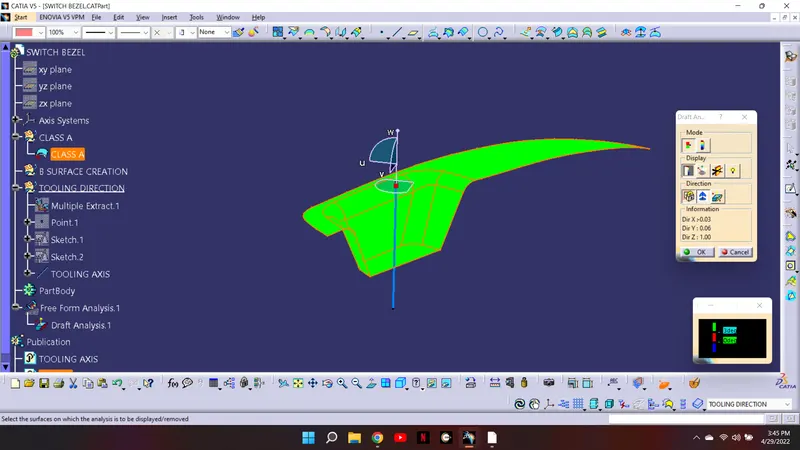
THE direction of the compass has been confidence with the tooling axis direction. The element that has been selected as the complete body
The draft satisfaction angle has been given as 2.9 degree which satisfies the complete model
DRAFT ANAYSIS FIANAL TRIM
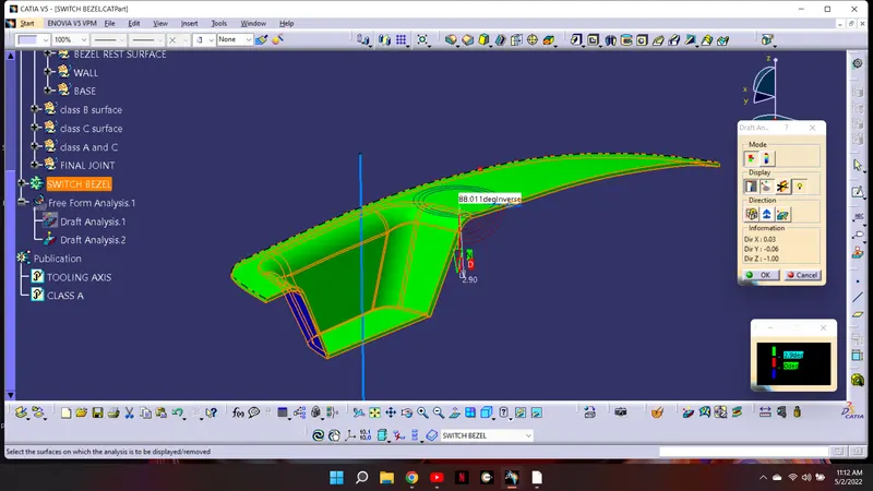
The dynamic draft runner has also shown to verify the body overall the body is safe and plastic part can be formed
THE FOLLOWING IMAGES ARE AS FRONT VIEW, SIDE, VIEW, TOP VIEW AND ISOMERIC VIEW