Week 8 - Challenge 5 - Core & Cavity Design
AIM
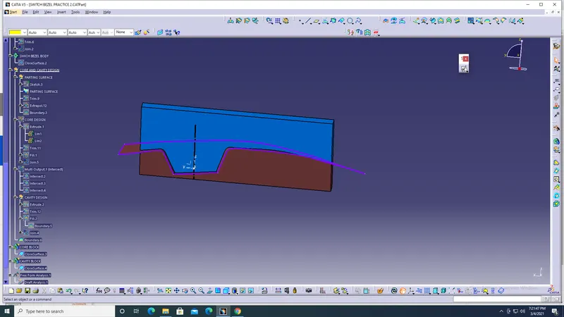
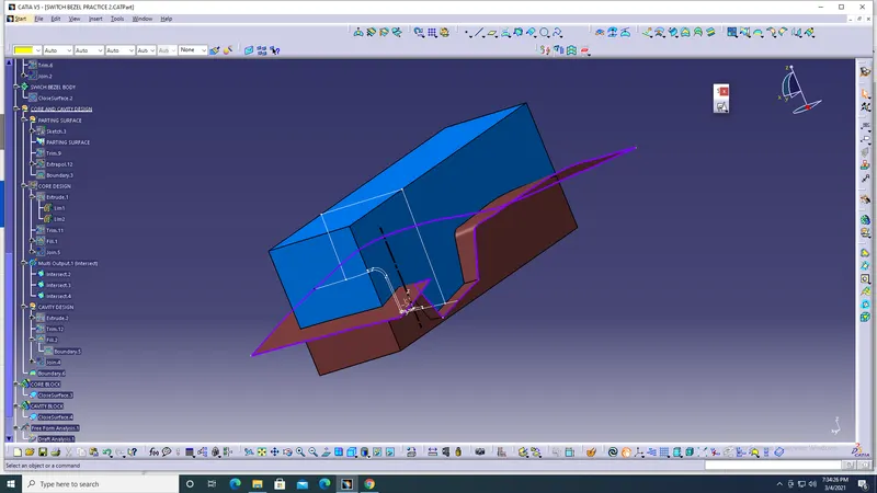
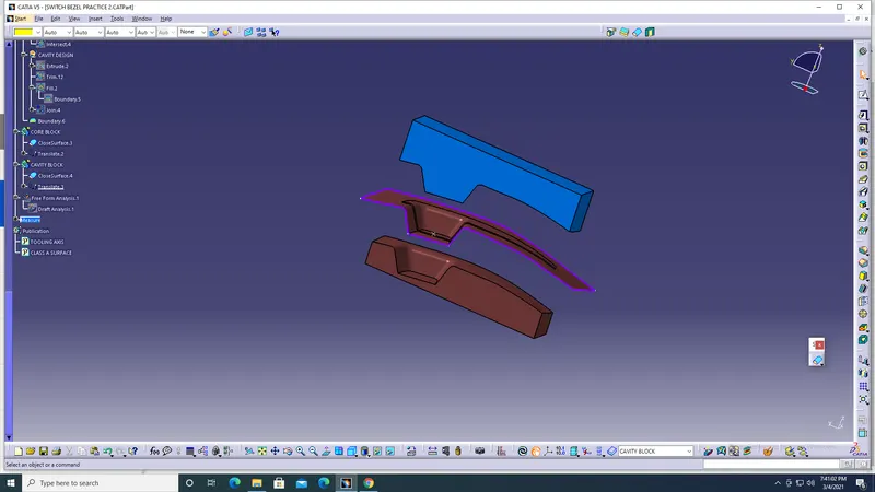
Create the Core and cavity blocks for the switch bezel designed in the earlier challenge. Parting Line and Parting Surface Detail report.
Introduction-
Tooling Axis
Here I'm doing the draft analysis and tooling axis creation .And also Develop the B and C surface with the help of A Class surface.
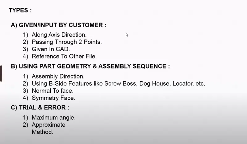
Tooling Axis - It is the direction or axis where two halves of the mold saparated to each other. The axis arround the core moveable with respect the cavity . In this axis choose by the different methode as given below
a. Given Input by the customer
b. Using part geometry and assembly
c. Trial error methode
1. Along axis direction
- Along axis Direction- Customer specifies to takes a tooling axis along the x, y and z direction.
- In this case you need to create one line using point and direction along the direction specified by customer . This will be your tooling Axis.
2. Passing Through The point
A. Costmer will give you only coordinates of two points.
B. In this case you need to create a line using point to point and this will be your final direction.
3. Given in CAD
Costmer will give you one tooling direction. And takes it as a tooling Axis.
4. Referance to Other file
A. costomer will tell yopu to draw a tooling with the referance of the other part.
B. In this case open that Old part And you need to copy the tooling direction and paste into the new part.
C. The create a line using point direction.
D. Create point on a surface and select old tooling as your direction.
5. Assembly Direction
A. In this case you have to takes assembly direction into consideration.
B. We must know the function of the Part to create a tooling Direction.
6. Using B side feature
A. If costomer does not given any data to related to tooling direction then you need to consider b surface Feature.
B. For Example If two screw bose given in B feature then you take the point on the center of scew boss and Create line passing through the point .
7. Normal to face
A. If there is a scew boss mounted on the B - side then Create a line normal to the surface.
B. You need to takes one point and select top surface of the Screw boss as a normal surface.
C. The line generated will be your tooling direction.
8. Normal to surface
If you think your plane is symmetrical the create the two mid plane and takes the and takes intersection .Find to tooling axis.
9. Maximum Angle
A. If customer does not given any data related to tooling axis and does not having any B side feature the we can try to this method
B. In this case we can findig the axis with help of draft analysis
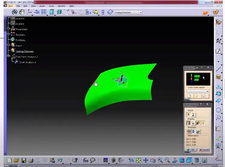
Draft Analysis
Draft Analysis-
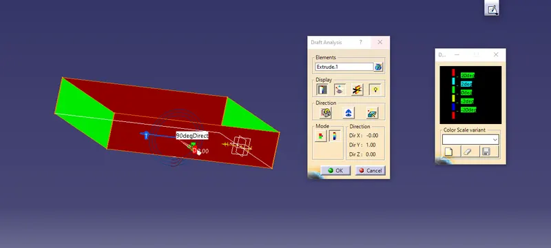
The Draft Analysis command enables you to detect if the part you drafted will be easily removed.
This type of analysis is performed based on color ranges identifying zones on the analyzed element where the deviation from the draft direction at any point, corresponds to specified values.
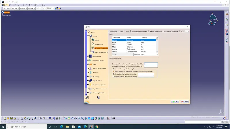
These values are expressed in the unit as specified in Tools > Options > General > Parameters > Unit tab.
You can modify them by clicking on their corresponding arrow or by entering a value directly in the field. As shown Below
This command is only available with:-
-
Part Design 1
-
Generative Shape Design 2
-
Wireframe and Surface for Building 1
- The discretization option should be set to a maximum: in Tools > Options > Display > Performances, set the 3D Accuracy > Fixed option to 0.01.
- On the Shading with matarial Mode go with the visual style.
- If No warning message if material mode is not ON option is cleared, the warning message is displayed asking you to set the Materials mode to ON. The material mode is not automatically set and not seen during analysis.
- The material is automatically seen for analysis. After completion of the analysis, the material mode returns to its initial state.
Process OF Draft anlysis-
- Click on Draft analysis command or Go through the insert option.
- The Draft dialog box is displayed. It gives information on the display (color scale), the draft direction and the direction values.
- The dialog box showing the color scale and identifying the maximum and minimum values for the analysis is displayed to
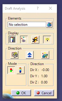
In DISPLAY Mode
- First is use for Show / hide of the Color Scale mode
- Second is the Analysis under the point where cursor move. Its show the draft angle at different point.
- Third reprsent no highlight of the shading mode .
- Bright the surface
Direction Mode
- Lock and onlock the Draft direction
- ON The Coompass for the new draft direction
- Change the direction of the Compass or inverse the draft direction.
Quick Analysis mode
The mode option lets you choose between a quick and a full analysis mode. These two modes are completely independent.
The default mode is the quick mode. It simplifies the analysis in that it displays only three color ranges.
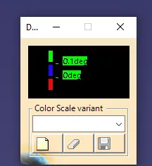
Full analysis Mode
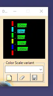
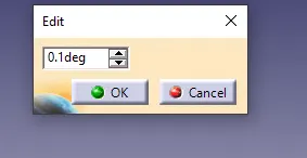
- Double-click on the value in the color scale to display the Value Edition dialog box.
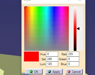
- Double-click on a color in the color scale to display the Color dialog box in order to modify the color range.
- Once you have finished analyzing the surface, click OK in the Draft Analysis dialog box.
- The analysis (identified as Draft Analysis.x) is added to the specification tree.
- Note that settings are saved when exiting the command, and redisplayed when you select the Draft Analysis icon again.
- Be careful, when selecting the direction, not to deselect the analyzed element. A draft analysis can be performed just as well on a set of surfaces.
- If an element belongs to an analysis, it cannot be selected simultaneously for
another analysis, you need to remove the current analysis by deselecting the
element to be able to use it again.
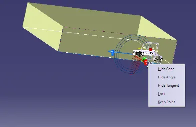
Right-click the Direction vector to display the contextual menu.
From the contextual menu you can:
-
Hide/show the cone.
-
Hide/show the angle.
-
Hide/show the tangent.
-
Lock/unlock the analysis position
A Class Surface
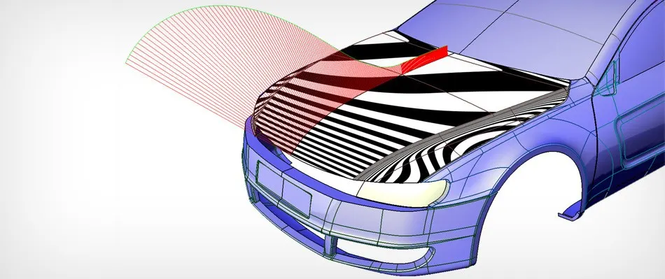
Class-A is a term used in specifically in automotive design. It describes the final production surface data for the aesthetic parts of the car. This is because as it achieves the highest surface quality levels, and it demands a high level of automotive design knowledge as well as surface modeling skills.A surface means visible surface.it will give style.
B Class Surface and C Class Surface
Class B surfaces are the secondary surfaces that you can see sometimes, but are less important, such as the inside of your glovebox, ash tray, etc. These must be smooth and "error-free" as well, but are not held to the standards that class A surfaces are. And the Surface which will connect Class A And B surface is called Class C surface.
Tooling Axis Creation
Step # 1
- First Check the Continuty of the A surface
- By using of the Join or Boundary command
STEP # 2
- Takes intersect of the plane by using of the Point , axis system and plane.
- Here we can not use bisecting method Beacause one surafce missing in zx plane
- Create a bisecting line with help of the intersect of zx plane
- Makes a sketch in xy plane and create line and use bisecting of available two and get the tolling axis
Publishing the tooling axis insert>Publishing.
- Extract all the surface of Class
- Untrim them
- Etrapolate them
- Takes offset
- And Trim and provide fillet and getting the B Surface
- Makes C surface
- By using of the Boundary of The A surface
- Extract The Boundary and Swip command which Join the A and B surface
- Provide Draft angle 3 Deg.
- And Join the A and C surface
- trim The Join and B surface
Check the Boundary should be closed.
Convert surface to solid
- Go in Part design and Go to closed surface Command and Convert the surface to solid
- Just hide the surface and get the solid This ready for Draft analysis.
Draft Analysis
- On the Shading Matarial Mode
- Click on the Draft analysis or Insert>Analysis>Draft analysis
- Select the body surface
- Click On compass direction and set on Tooling axis
- Watched the color and accordingly chnage the Draft angle or change the tooling direction
- And get the final result
Hare I'm Design cor and and cavity
Parting Line
A parting line, in industrial casting of molds, is the border line in which draft angles change direction. That is, it is the dividing line that splits the core and cavity halves of a molded part. It is sometimes a starting point for the mold parting surface.
Parting Surface
A parting surface is a surface that separates the mold block into two parts – the core and the cavity.
Process to design Core and Cavity
- First take A surface for the for doing draft analysis but here i am going for the core and cavity design.
- Extract the A Surface.
- Untrim the A Surface and Extrapolate the A surface.
- Unhide the C Surface and trim with Extrapolated surface and then with B surface .
- Unhide the B surface for Makes parting surface.
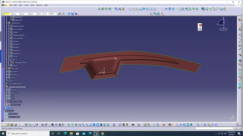
- Sketch the surface On parting and cover the body and Extrude the surface of sketch.
- And Untrim parting line and extrude surface.
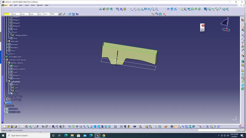
Convert surface to solid and geting the core .
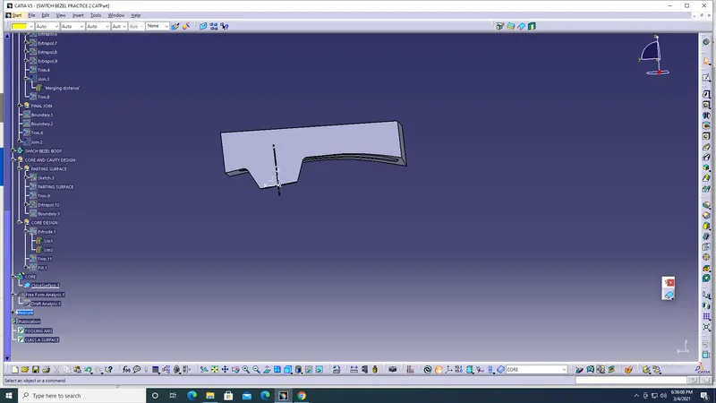
Simlarly convert the cavity.
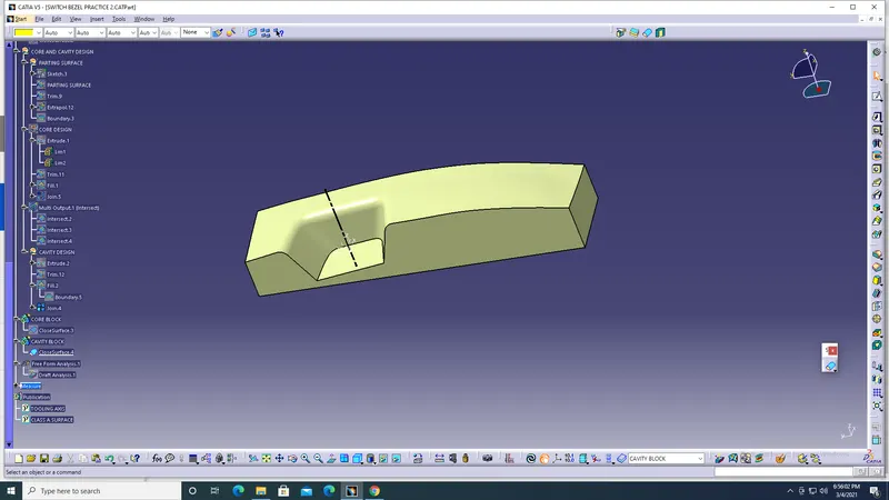
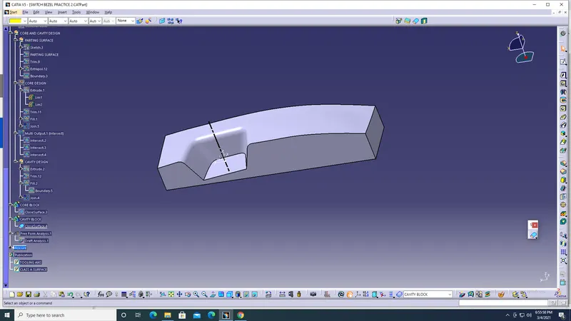
Here parting surface b/w the core and cavity and saparates the core and cavity. and the boundary of parting surface is called parting line.