Week 8 - Challenge 5 - Core & Cavity Design
Design of Core & Cavity
Draft Analysis - It is a tool that allows the user to ‘see’ whether the part they are designing can be removed from the tool being used to make it. In the case of plastic injection molded parts it also allows the designer to see if there is enough draft on the part to ensure that it can be correctly grained. I always use the tool with the axis direction method. Put the main axis on the draft direction line with Z being parallel to it. Select the tool then select the part body. You may need to reposition the axis again. The results window has 2 options 1 with just 3 color variants and the other with many variants. They can be edited by double-clicking on them to give you the result you desire. The colors show the different draft angles.
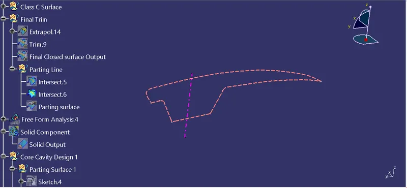
Parting Line - The parting line separates components from the rest of the mold. Also, it separates the core and cavity halve.
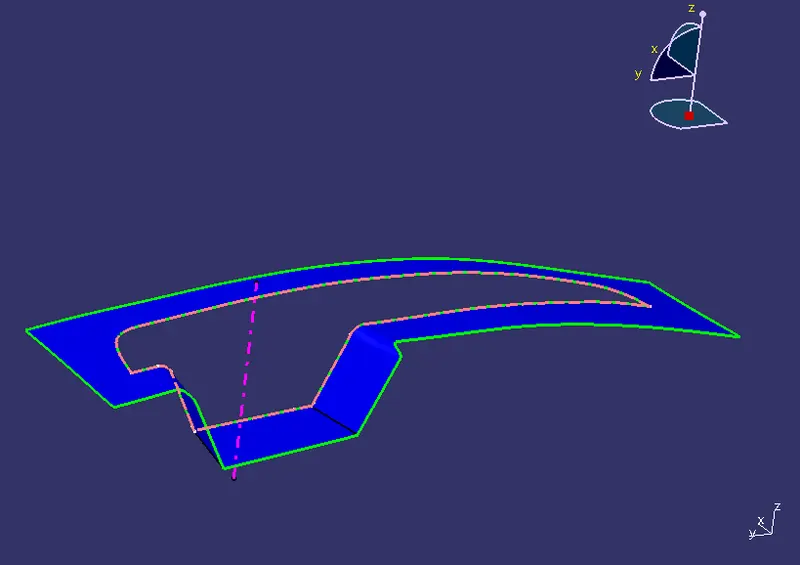
Parting Surface - The surface which separates the core and cavity without the component.
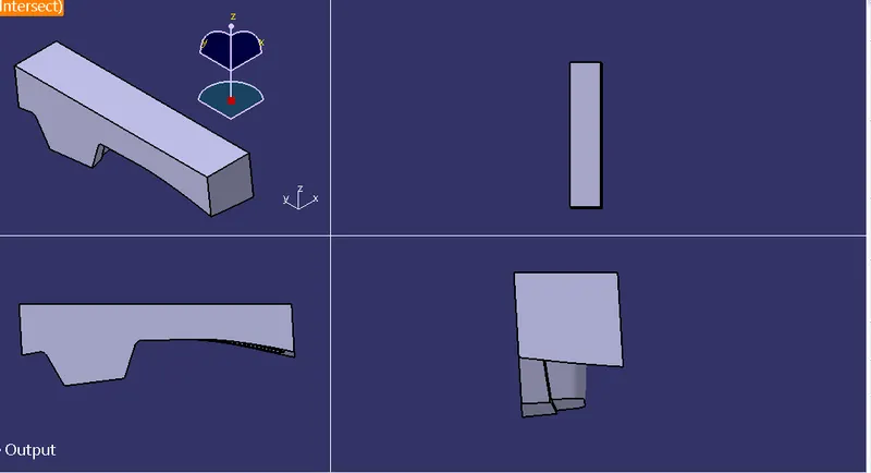
Core - It is the projection half of the mold.
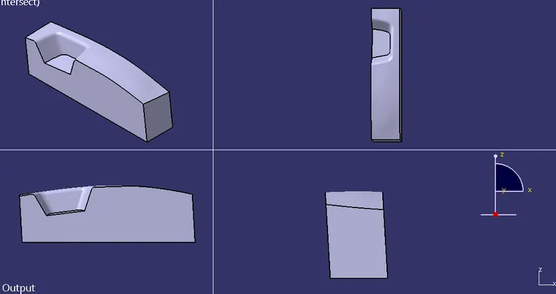
Cavity - It is the depression half of the mold.
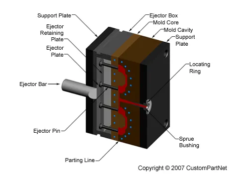
Mold - A mold is a hollow metal block into which molten plastic is injected from a certain fixed shape. Although they are not illustrated in the figure shown below, actually there are many holes drilled in the block for temperature control by means of hot water, oil, or heaters.
The molten plastic flows into a mold through a sprue and fills cavities by way of runners and gates. Then, the mold is opened after the cooling process and the ejector rod of the injection molding machine pushes the ejector plate of the mold to further eject moldings.
Procedure
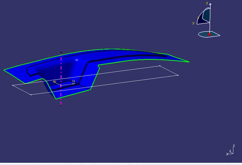
Creating Parting Surface
- Extract class A surface boundary lines then extrapolate them by 15mm.
- Trim the extrapolated surface with class C & B surface.
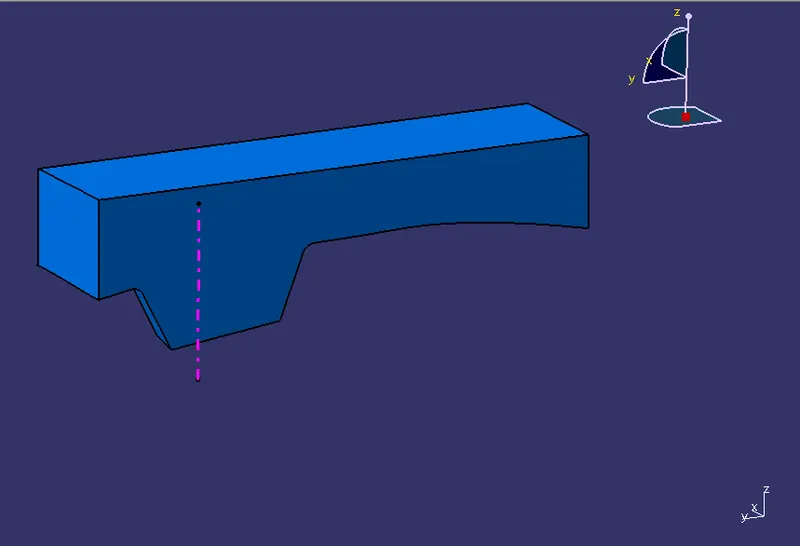
Procedure for core Design
- Create a new sketch in XY plane
- Draw a rectangle and constrain it then extrude it from both directions.
- Trim it with parting surface then perform fill operation, and join them together. Open part file and insert body then convert into solid.
Design of Cavity
- Trim the extrude surface with b surface.
- perform fill operations and join them together. Open the part file and insert body then form solid.
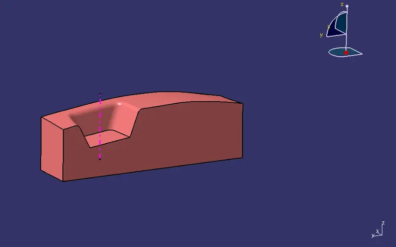
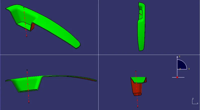
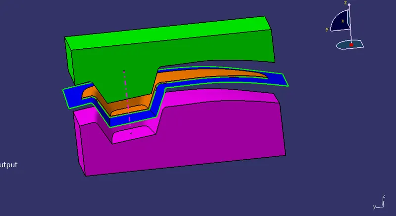
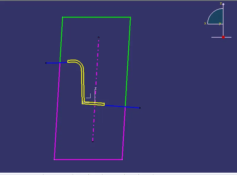
Getting a clear insight into thickness and study of our mold design through the intersection method.
Yellow Colour - Component
Green colour - Core
Violet Colour - Cavity
Dotted axis is the tooling axis.
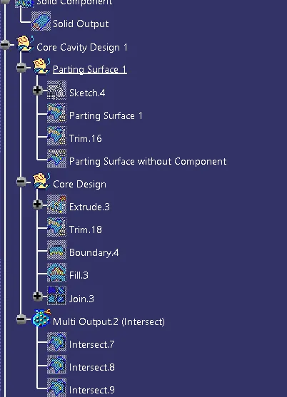
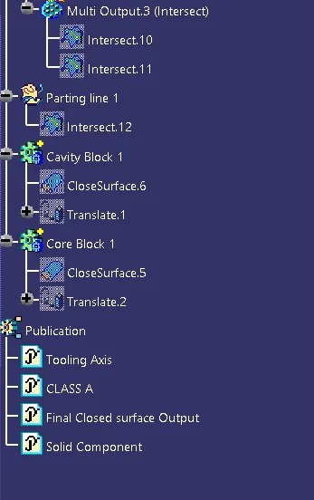
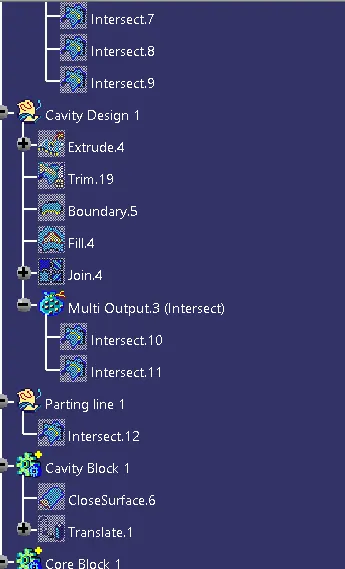
Tree Structure