Week 8 - Challenge 5 - Core & Cavity Design
CORE AND CAVITY DESIGN
1. Tree Structure and The Geometrical Sets
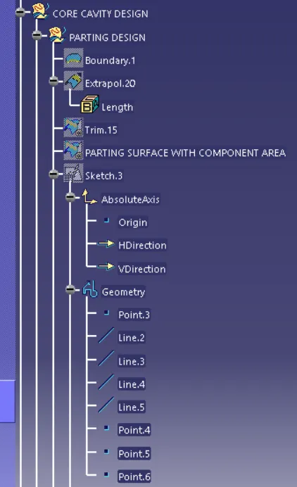
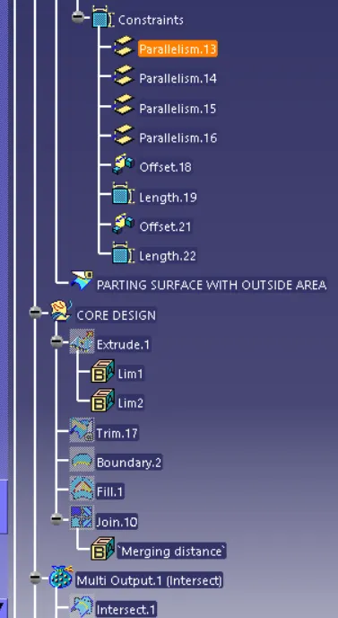
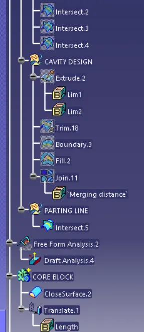
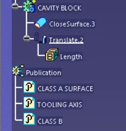
2. The Various Oreintation View of the Core and Cavity
- Front View
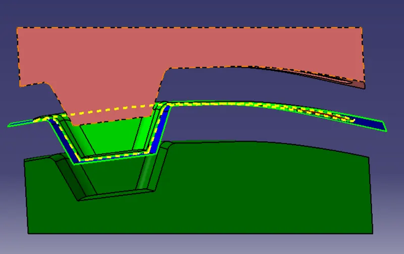
- Side View
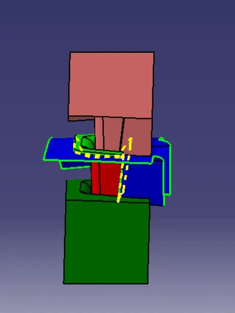
- Top View
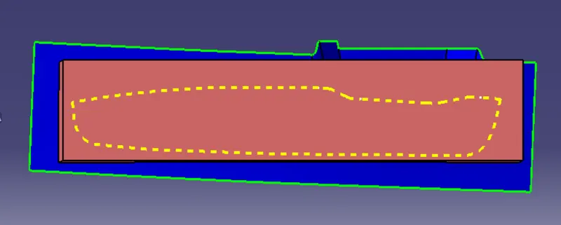
- Isometric View
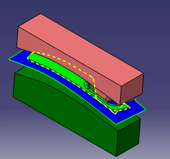
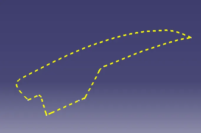
- Parting Line
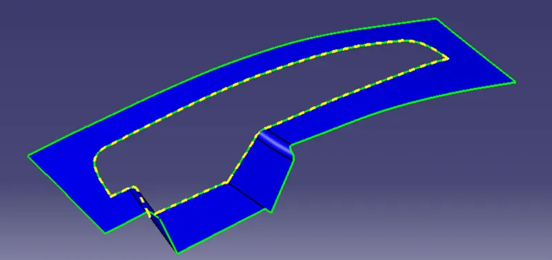
- Parting Surface
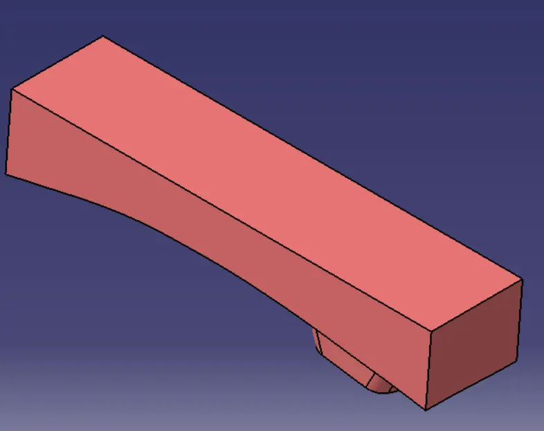
- Core Block
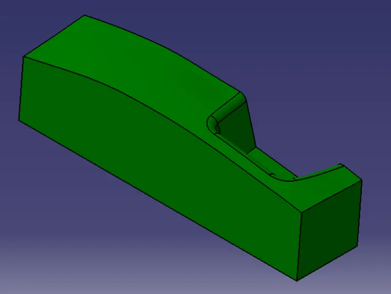
- Cavity Block
- Tooling Axis
The Tooling axis which is use in the switch bezel it has been use for the Core and Cavity Design
Tooling axis for Y direction
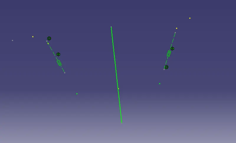
Tooling Direction For X Axis
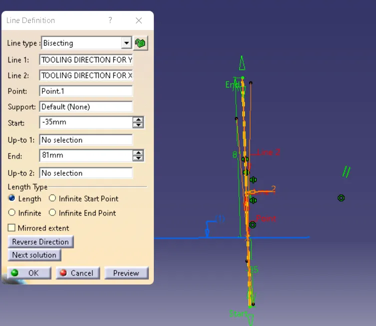
Main Tooling Axis
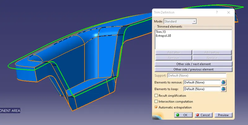
- Parting Surface Design
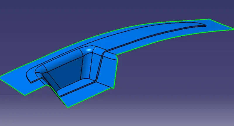
Trim the Class A Extrapolate with C surface to create the inner parting Surface
- Parting Surface For the Inner Component
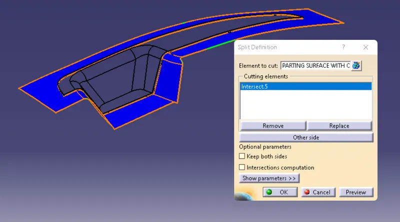
- Parting Surface for the Outter Component
- Core Side Design
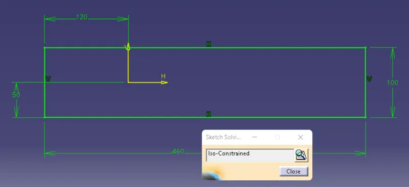
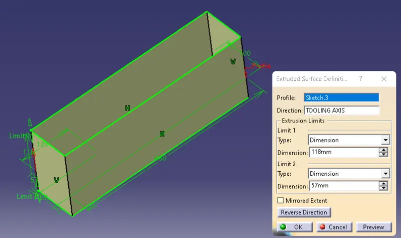
Create the sketch for the cavity block Extrude the Rectangle Shape
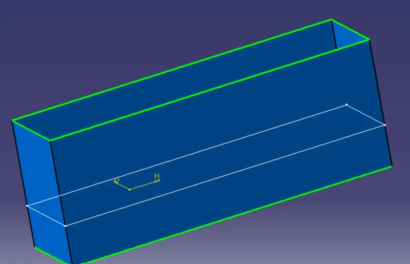
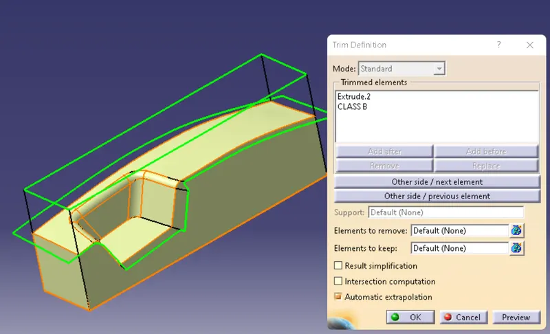
Trim the extrude surface to the outer Component
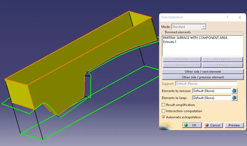
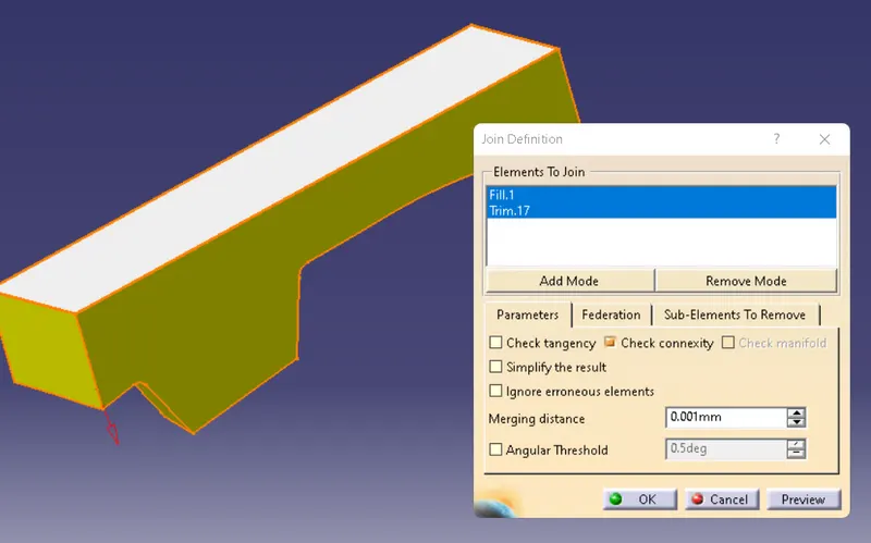
Close Body of Core Side
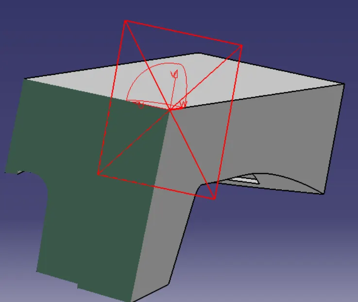
Multiple intersection Output
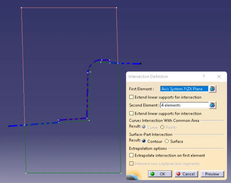
- Cavity Side Design
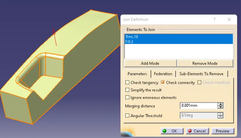
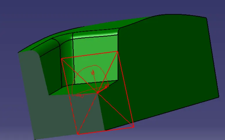
Close Body of Cavity Side
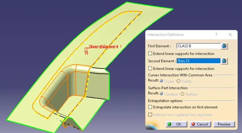
- Parting Line
Draft Analysis Core And Cavity by using the Switch Bezel
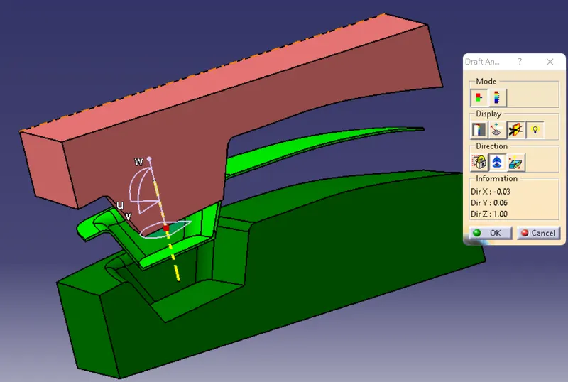
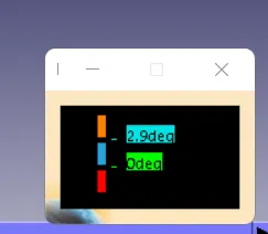
The Minimum draft angle is 2.9 degree for the Switch Bezel
- Detailed Report for the Core and Cavity
Tooling axis is shows which side the component going to be draft,the tooling axis will use in the Switch Bezel
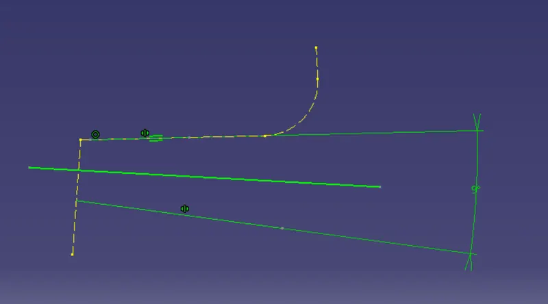
First Create the Sketch tooling axis for Y Direction,
In the sketch intersect with the Class A Surface and draw two line and bisect the LIne and Create the other sketch for the X Direction Tooling axis
in the skech also intersect with the Class Surface.
Bisect the X and Y Direction tooling axis make It main tooling Axis.
Parting Surface
Create the Boundary By using the Class A Surface and Extrapolate the surface and trim with the C Surface to form a Parting Surface with Inner Component Area and for outter component area intersect with inner Component
Cavity Side Block
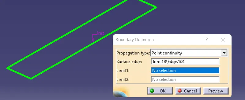
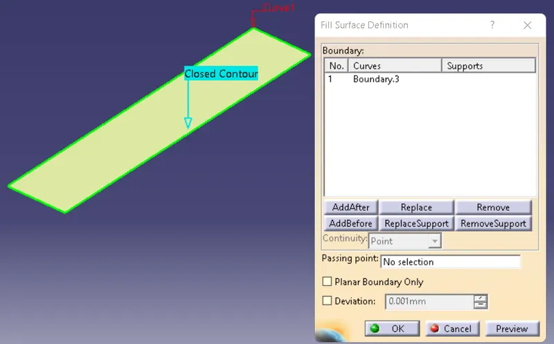
Create a Rectangle Extrude Surface For the cavity block and trim with the class B, Create the boundary at the bottom and fill the Surface then join the surface and insert body make solid Closebody.
Core Side Block
Use the Same Sketch which is use in the cavity block and extrude the surface trim with inner parting surface, then fill the top surface with Fill Component, Join both the Surface , and Insert body create solid Closesurface Body.
Parting Line
Intersect the Class B and Class C jion with Class A it is the Parting LIne.