Week 8 - Challenge 5 - Core & Cavity Design
REPORT - DESIGN OF CORE & CAVITY FOR SWITCH BEZEL PLASTIC PARTS
INTRODUCTION-
In automobiles required plastic parts are manufactured with the help of mould.The mould contains core and cavity sub components which is projection and impression of actual parts resp.
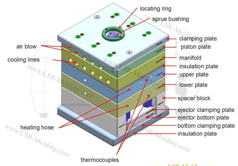
MOULD- Mould is assembly set of different sub components that used for production of plastic parts in mass range.The sub componens are as follows-
- SPRUE
- SPRUE BUSH
- LOCATING RING
- UPPER PLATE
- LOWER PLATE
- EJECTOR PIN
- EJECTOR PLATE
- SPRINGS
- SPACER BLOCK
- PILLER-BUSH
- COOLING CHANELS
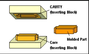
- CAVITY- It is solid block of part that we have to produced.Cavity is a impression of plastic part.Cavity is fixed part of mold.
- CORE- Core is produced from part by taking projection of part surfaces.Core is a movable part of mould.
PROCEDURE -
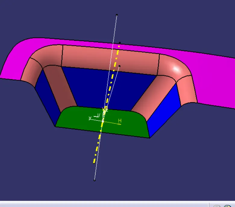
*Procedure to create TOOLING Axis by using BISECTING method-
The bisecting method generally used for tapered object or part which having drafted feature with some angles.For that tapered part we have to decide correct tooling axis and which is very difficult.
In switch bezel we see mostly plane surfaces and intersecting surface found in Y-direction only.Also there is plane base intersecting to wall surface is found.
So that we have to create tooling axis with bisecting the line1 which is normal to base surface and line 2 which is 3 degreedeviate to coinsidence line of class A intersecting surface.
To create TOOLING AXIS go to LINE>BISECTING>select>line1 & line2>select intersection piont>OK.
1.Open part-To creating Tooling part we have to open the part that have CLASS-A Surface.
2.Geometric Set- we creating geometric set,in that all sketches should be involved.
3.Boundary surface- To create tooling axis it is first step to create the boundary by selecting surface.Here we have to get the 3D sketch of part.
So go to SHAPE>GENERATIVE SHAPE DESIGN>OPERATION TOOL >Select BOUNDARY.
4.Extract base surface-To getting Tooling Axis we have plane base surface on Class A-surface so by extracting base and creating point and normal line with help of new axis system.
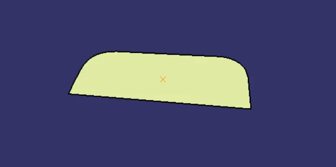
5.Tooling Axis- To obtain the tooling axis,we have to select both normal line 1 and deviated line 2 of intersecting line surface Which gives us the combine form of these axis and this axis is called as Tooling Axis.
go to line>bisect line>select line 1&2>Select point>ok
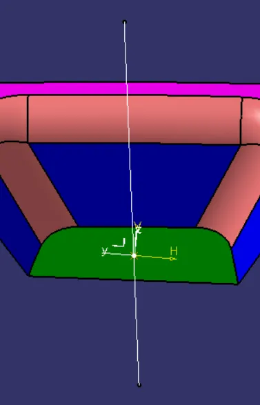
Feature tree chart-
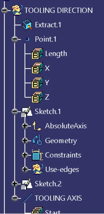
So that in this way by using Bisecting method we can create the TOOLING AXIS.
Now after creating tooling axis we can move for Draft angle Analysis.The procedure of draft analysis are as followes.
**CORE & CAVITY DESIGN PROCEDURE-
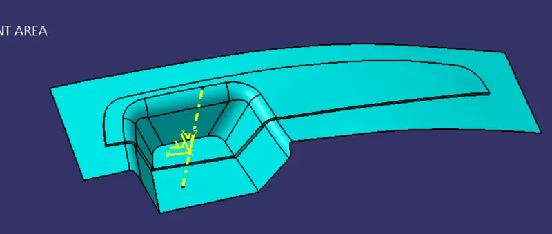
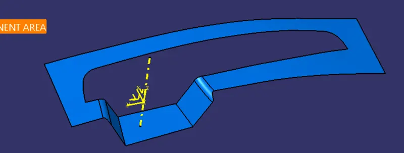
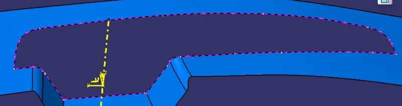
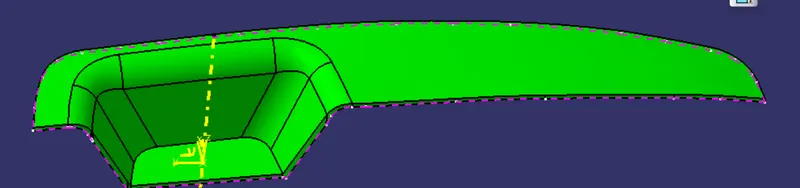
A) PARTING SURFACE GENARATION-
- Extrapolate the Class A-surface with suitable distance.
- Trim the class A-surface with Class C-surface alon with Class B-surface which will gives parting surface with coponent area.
- Split the parting surface of component area with parting line which will give parting surface.
B) PARTING LINE-
- Intersect the final join of part with class b-surface,result of it gives boundary line to the part geometry is called parting line.
C) CORE DESIGN-
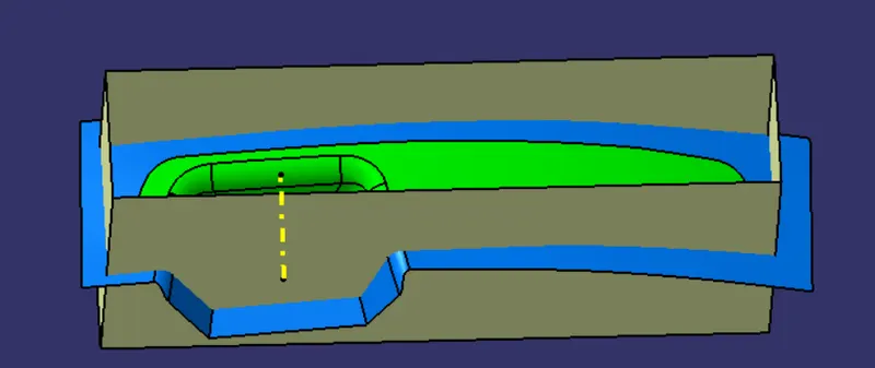
- Sketch the rectangle block on parting surface and extrude it.
- trim the extra part of extrude surface which below the parting surface.
- Fill the upper surface and join the trim and fill surface
- Make the core surface into core solid block by using part workbench.
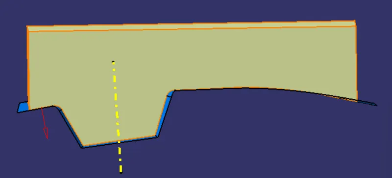
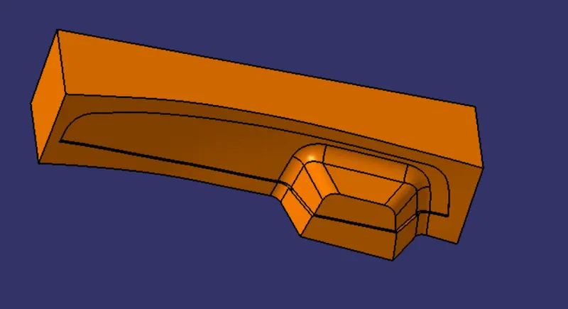
D) CAVITY DESIGN-
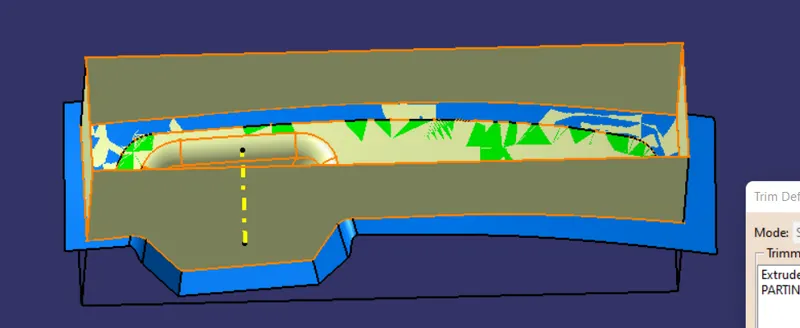
- Sketch the rectangle block on parting surface and extrude it.
- trim the extra part of extrude surface which below the parting surface.
- Fill the upper surface and join the trim and fill surface
- Make the cavity close surface into cavity solid block by using part workbench.
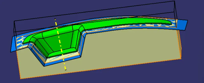
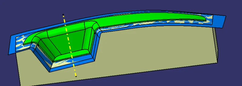
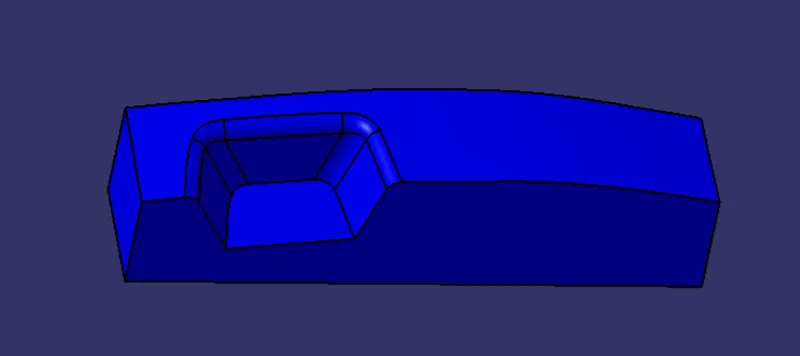
E) INTERSECTING SURFACES-
- Intersect the parting surface with core and plastic components to obtain core 2D intersection sketch.It will give clear understanding of parting line and component boundary intersection status.
- Do same for cavity block to check the status of intersecting geometry which is correct or not.
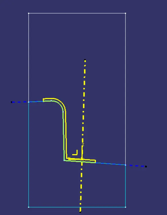
**Procedure to create Draft Analysis-
1.Open the part file in Catia workbench.
2.Apply the material for part.For that go to view feature>Render style>Customize view parameter.
3.For draft analysis we have to select Insert>Analysis>Feature draft Analysis.Then there will be opening the Draft analysis dialogue box with showing icons like mode, display and direction.
4.Move the compass towards the tooling axis and coinside it with tooling axis.If you want to fix the compass then click on lock icon .
To start the analysis-
1.Select the surface of Part that we want to analysis.
2. click on draft analysis icon .
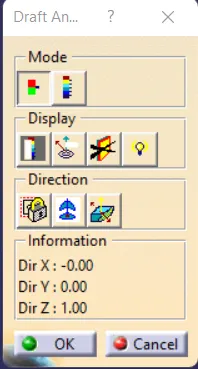
3.MODE OPTION-
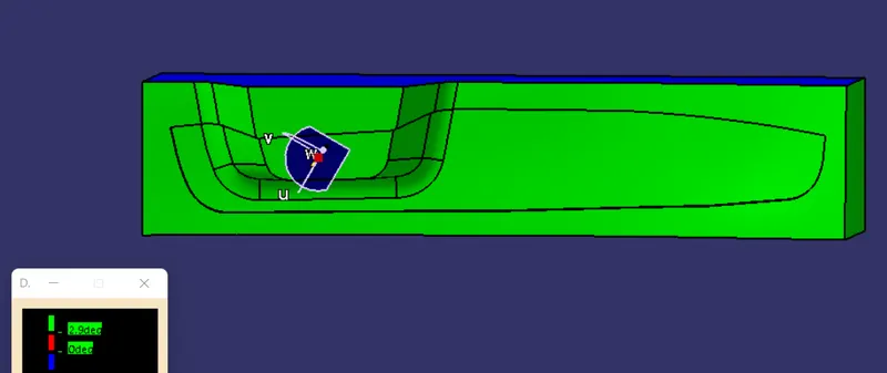
In dialoue box showing mode option with quick & full analysis mode.In that mode feature we can understand the different angle range value in colour format which indicate part is in correct drafft mode or not.
The default mode is the quick mode. It simplifies the analysis in that it displays only three color ranges.
* QUICK MODE-
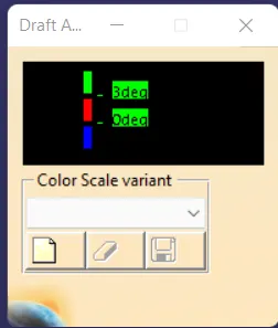
*FULL MODE-
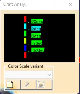
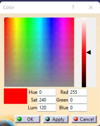
* Doble click on colour range which display in dialogue box and we can change the colour range.
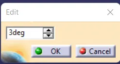
*Also by double click on the angle value ,we can modify it.
*The colour mode and respective Draft angle value is set in mode dialogue box.
- When the Draft angle value of the surface is equal or smaller than graduated (fixed in dialogue box) value,the colour will be applied as per graduated value to the surface.
- When the Draft angle value of the surface is greater than greatest value of graduated,the colour of graduated value is applied.
4.DISPLAY OPTION-
- colour scale-this dialog box only appears in edition mode.Means we have to activate Full mode or Quick mode analysis.
- Angle Pointer-activate the pointer and move it over the surface which showing various draft value at different locations.
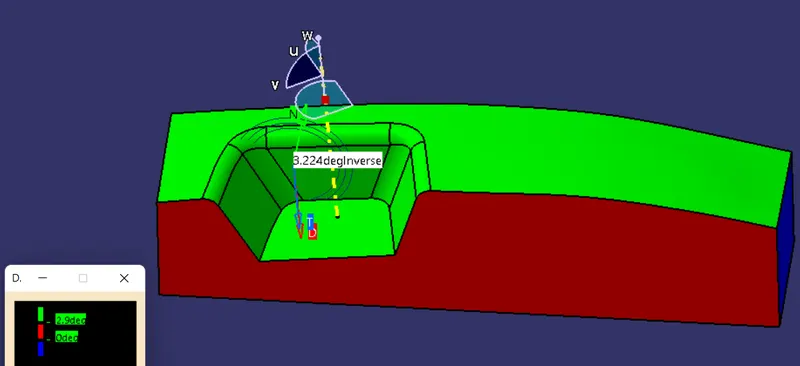
Arrows are displayed under the pointer, identifying the normal to the surface at the pointer location (green arrow), the draft direction (red arrow), and the tangent (blue arrow). As you move the pointer over the surface, the display is dynamically updated. Furthermore, circles are displayed indicating the plane tangent to the surface at this point.
3.No highlighted & Representation icon-This feature gives option like on/ off the highligh portion of part.As it enable ,it will show all edges in colour (highlight) format.
4.LIGHT EFFECT-This feature helps to understand the visualisation effect of part under light effect.This light effect will affect the visualiser's eye.
5.Inverse direction- It allows to change the direction of draft angle of selected part.As the we click on reverse direction then there is changing gaduated colour effect ( in negative).It shows the BLUE colour.
5. DIRECTION -
- LOCKED DIRECTION- In that we can lock or unlock the draft angle direction,a plane,a Face which is used in current analysis.
- COMPASS- It is used to define the new or current draft direction.To set the compass direction on Tooling Axis,we have to move or pull the compass origin and coinside with tooling axis.
6.Once we have finished the analysing the surface by applying propper elements CLICK on OK icon in DRAFT ANALYSIS DIALOGUE BOX.The analysis is added to tree chart of part.
IN this way we can genrate the report for Draft Analysis for a given part by using Feature Draft Analysis.
The images of Draft Analysis are as follow-
1.Quick Analysis mode- with color scale variant & Complete draft Analysis
A) CORE BLOCK-
B) CAVITY BLOCK-
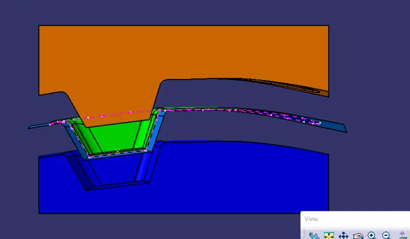
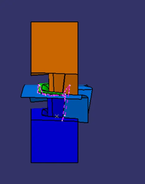
*Different orintation views of switch bezel with core and cavity-
*Front view-
*Side view-
*TOP VIEW-
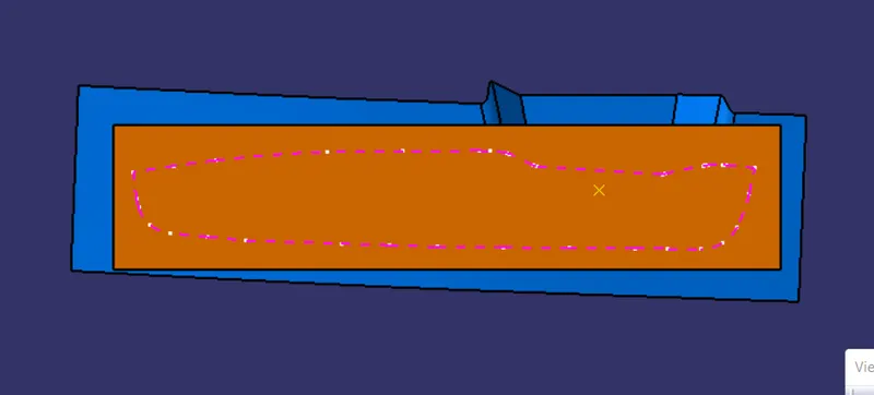
*ISOMETRIC VIEW
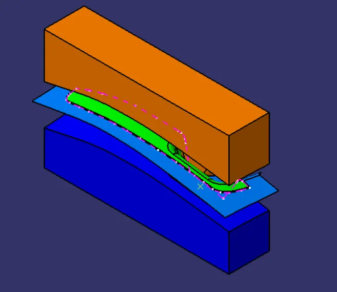
**CLOSE VIEW WITH COMPONENT-
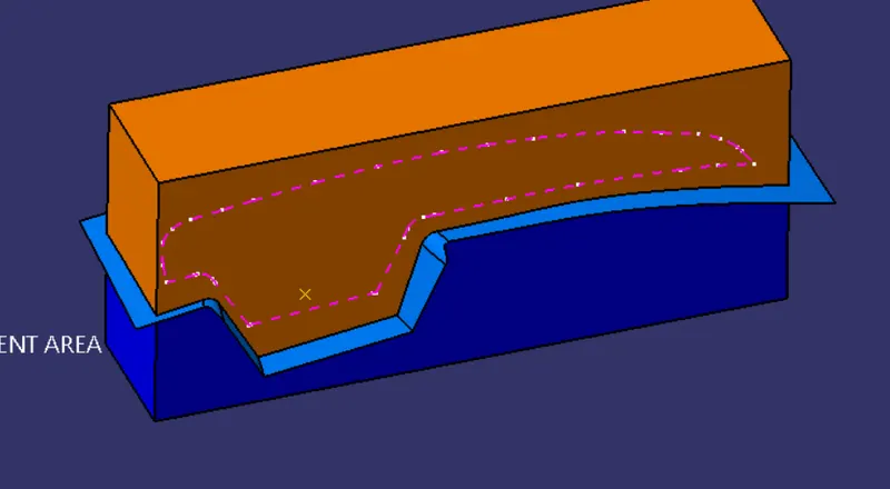
**RESULT OF ANALYSIS-
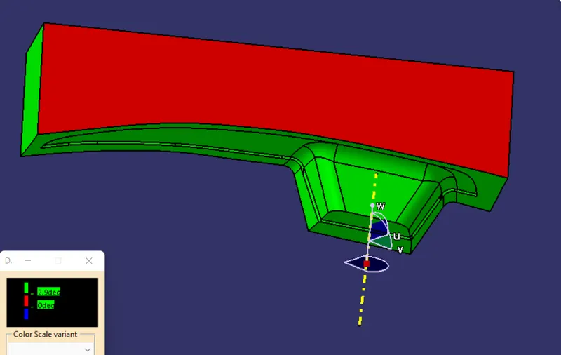
1.GREEN COLOR- Here Green color shows that the draft analysis is positive and there is no error in model.The angle more than 3 degree is considered as positive draft angle.The core will be easily eject from component and cavity
2.Blue & Red Color- Red and Blue color shows negative draft angle.
** CONCLUSION-
- Learn about mould and its components and functions.
- learn to importance of core and cavity in mould tool.
- learn to create parting surface as well parting line to create core and cavity in CATIA V5.
- learn to generate drafting report for core and cavity as well plastic component.