Week 8 - Challenge 5 - Core & Cavity Design
AIM: To Create the Core and Cavity blocks for the Switch Bezel Design.
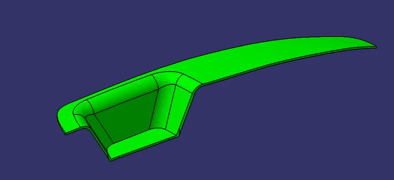
PROCEDURE FOR CREATING CORE :
STEP 1: Extract Boundary from A class.
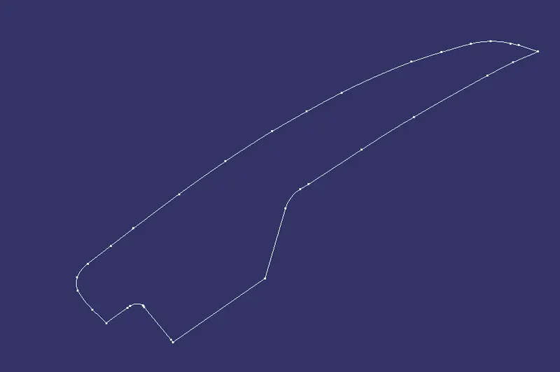
STEP 2: Extrapolate the boundary.
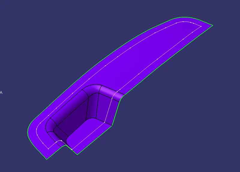
STEP 3: Unhide the C surface.
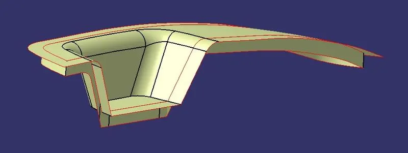
STEP 4: Trim extrapolated surface with C surface.
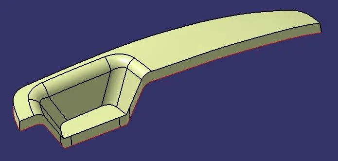
STEP 5: Unhide class B surface.
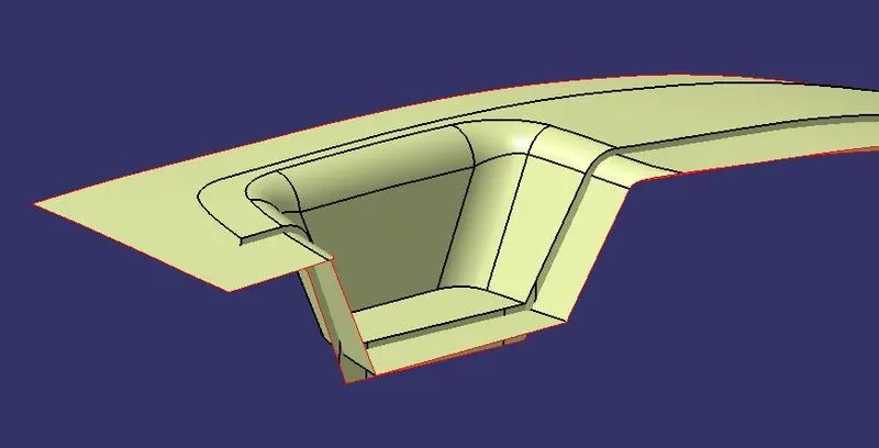
STEP 6: Trim the last trim with class B surface.
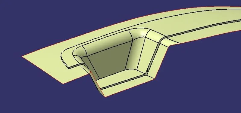
- This will be called a Parting surface with component area.
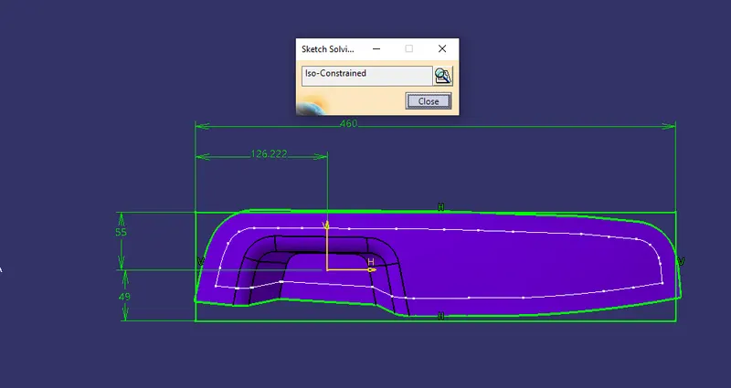
STEP 7: Sketch a rectangle inside the surface and it will be the dimension for the core.
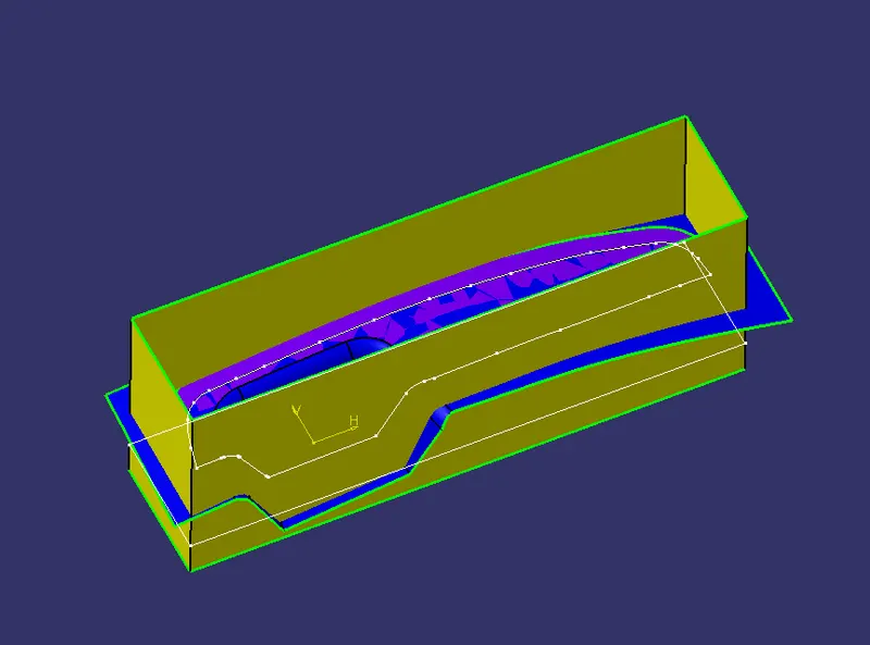
STEP 8: Extrude the sketch from both directions.
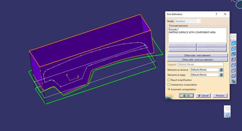
STEP 9: Trim the extrude with parting surface with component area surface.
STEP 10: Fill the remaining boundary with the fill surface option and join it.
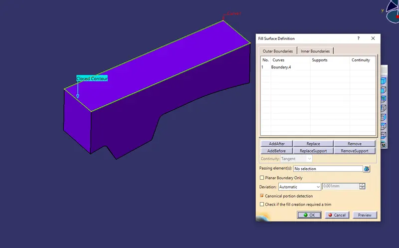
STEP 11: Switch to Part Design Workbench, Define Part body to make Core C Surface into a solid component by close surface panel.
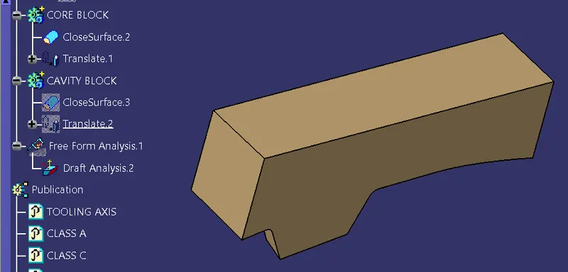
PROCEDURE FOR CREATING CAVITY :
STEP 1: Unhide class B surface and rectangular extrude.Or create new rectangular extrude with the same sketch that we have.
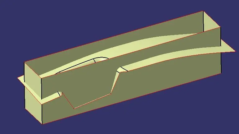
STEP 2: Trim class B surface and rectangular extrude from below to make it cavity.
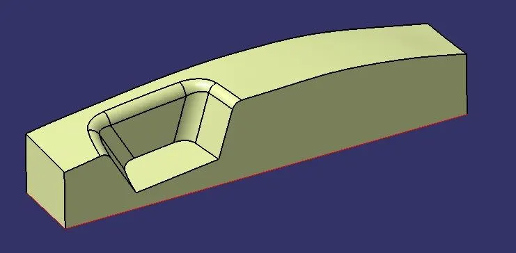
STEP 3: Fill the remaining boundary with the fill surface option and join it.
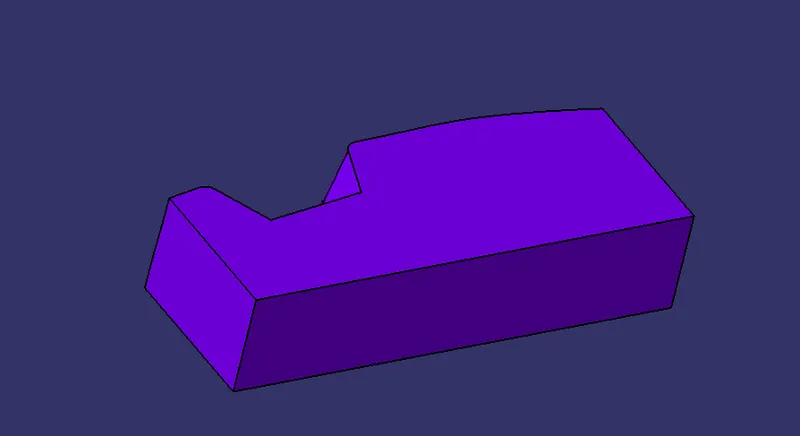
STEP 4: Switch to Part Design Workbench, Define Part body to make Core C Surface into a solid component by close surface panel.
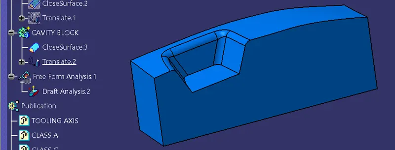
THEORY :
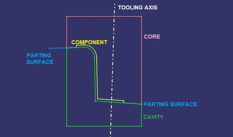
- We can see the sectional view of the core and cavity which has the void area where melted plastic will be filling.
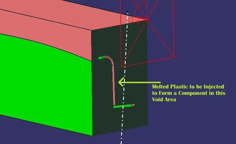
- Intersection view of ZX plane with core, cavity, component and parting surface.
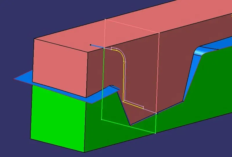
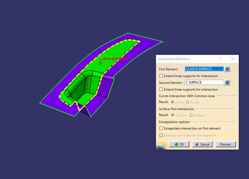
- To get a parting line we can intersect the C surface with the B surface.
Core : The core is the male part which forms the internal shape of molding, the upper half of the mold where the tool where the plastic part is injected from is called core.
Cavity : The cavity is the female part which forms the external shape of molding.
Parting Line : The parting line of a die cast component represents where the two different sides of the mold come together. This line often marks the border between the inside and outside of the part. The location of the parting line indicates which side of the die is the cover and which is considered the ejector
Parting Surface :A parting surface is a surface in the model that you designate to split a workpiece, die block, or another volume. It is designed for the removal of the plastic product and the cold slug, the parting surface is where the core meets the cavity, and usually located at the largest section of a product.
Tooling Axis : Tooling axis is the direction in which mold or core and cavity is opened.
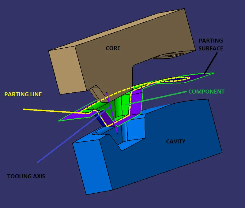
- Translated View of Model.
LEARNINGS :
- Creating Core
- Creating Cavity
- Parting Surface
- Parting Line
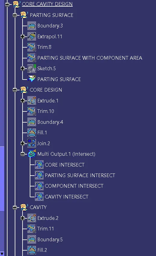
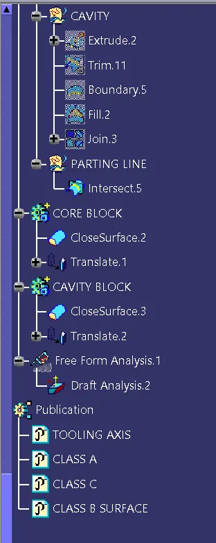
TREE STRUCUTURE:-
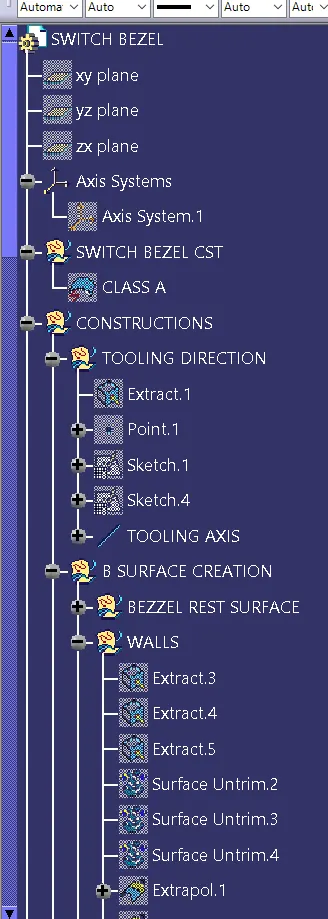
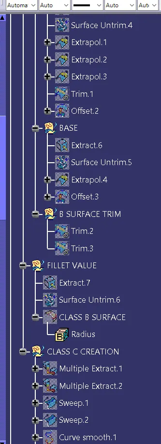
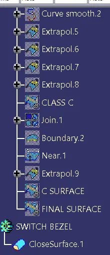
CORE CAVITY DESIGN TREE STRUCTURE:-