Week 8 - Challenge 5 - Core & Cavity Design
Design of Core and Cavity block for Switch Bezel
Objective:
- Make Core and Cavity for the Switch bezel
- Mark the Parting line and parting surface
Switch Bezel:
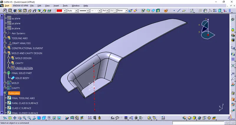
Creation of the tooling axis:
A surface is extracted from the base of the cavity and a point is created at the center of the surface. A axis system is created on the point.
A sketch is created and an intersection sketch is created on the surface
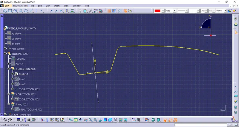
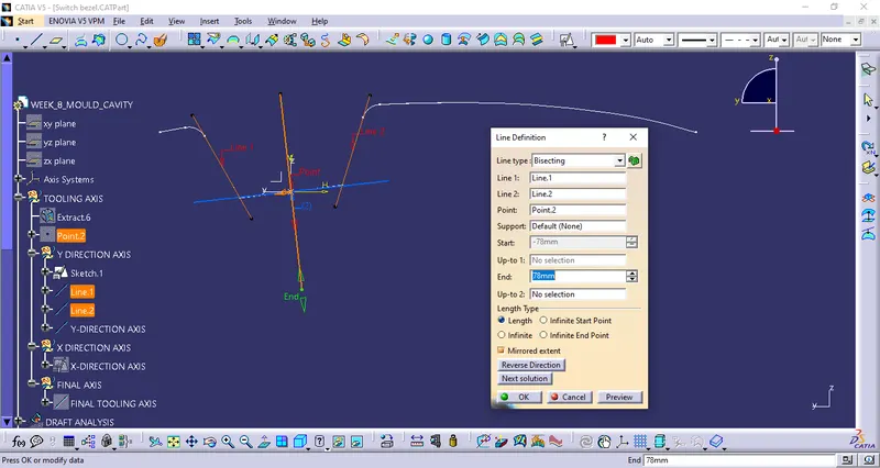
Two lines are created on the two inclined walls of the, using the bisection command in the line command a line is created
This is the Y-Direction tooling axis:
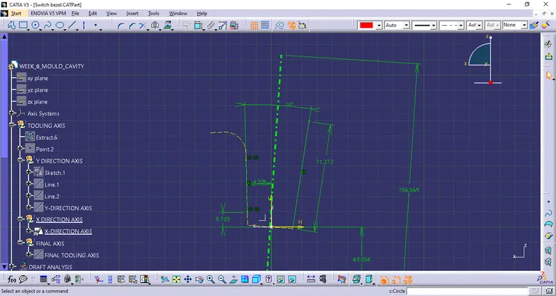
A sketch is X-Direction and a bisecting line is created on the sketch.
This is the X-Direction tooling axis:
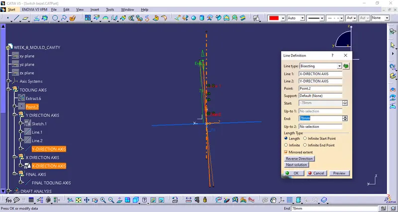
To make the final tooling axis, both X and Y tooling axis is bisected using the bisect option.
Draft analysis:
Using free form analysis and the tooling, draft analysis is performed on the solid part
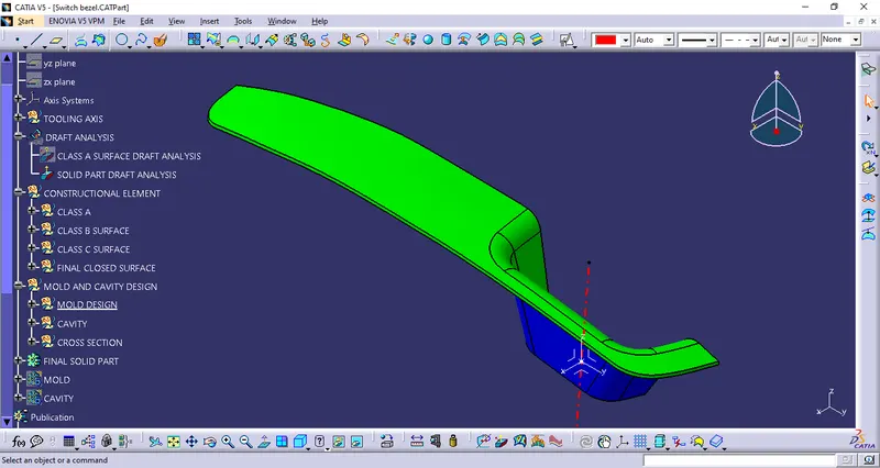
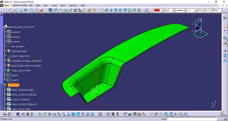
The part has positive draft
Making mold and cavity:
Mold: The mold is the shape of the part which will go inside the cavity of the part
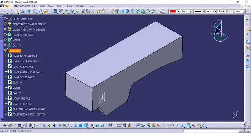
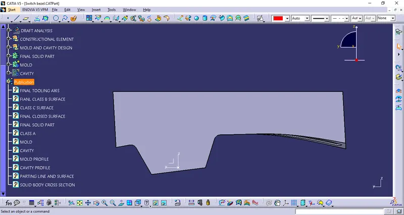
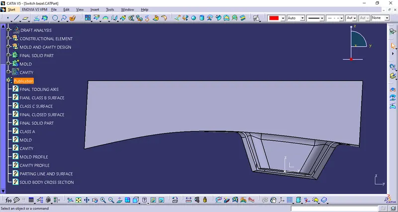
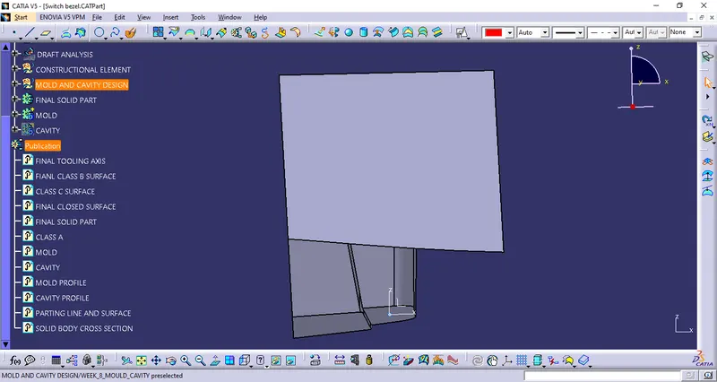
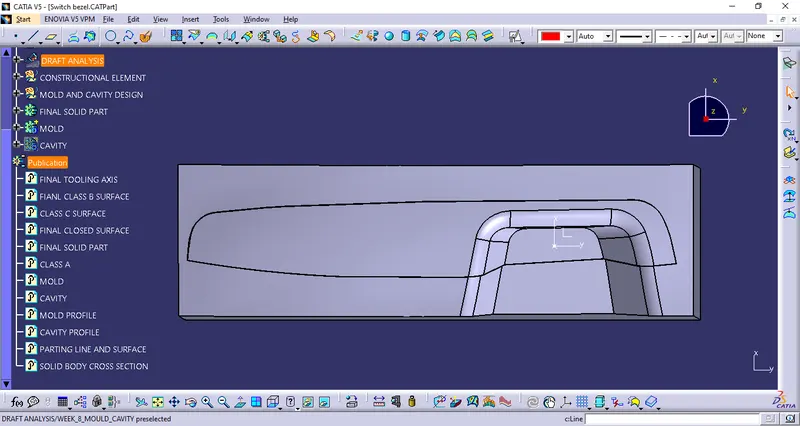
The mold has space of 2.5 mm to allow the plastic to flow in and take the shape of the switch bezel
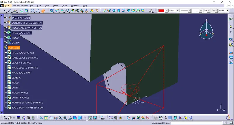
Cavity:
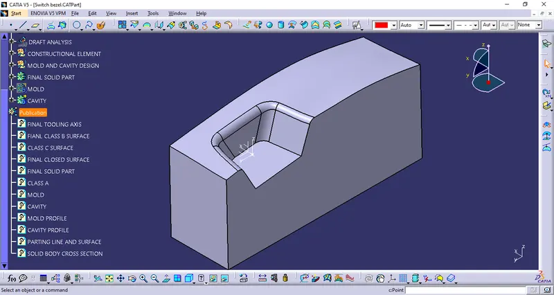
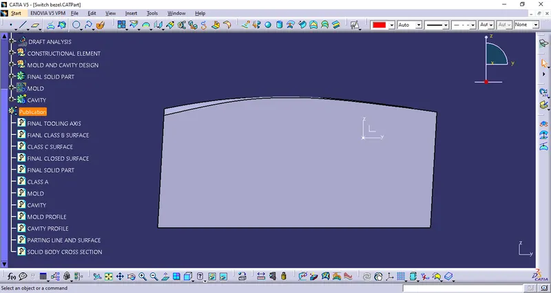
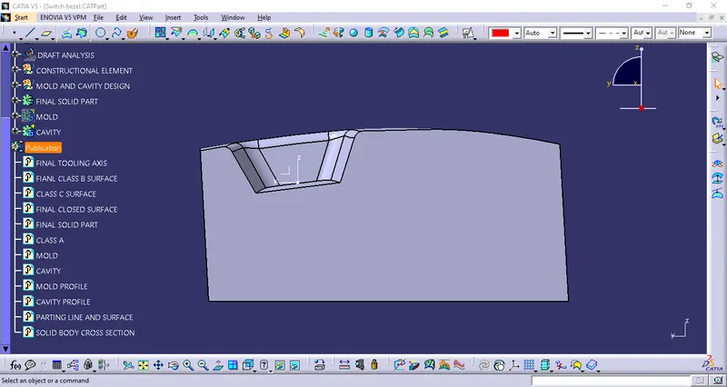
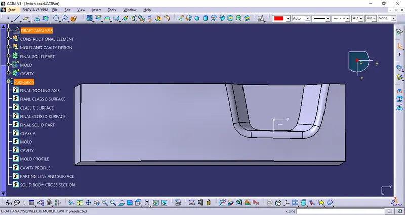
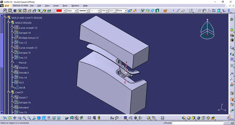
Mold and cavity closed together to make the shape of the part:
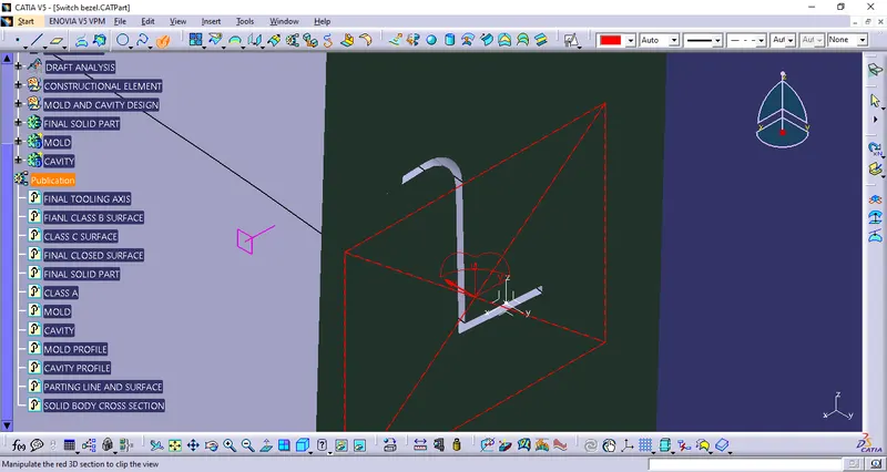
Parting line and Surface:
The parting line is the line where mold and cavity seperate, the surface formed at that line is called the parting surface.
Paritng line:
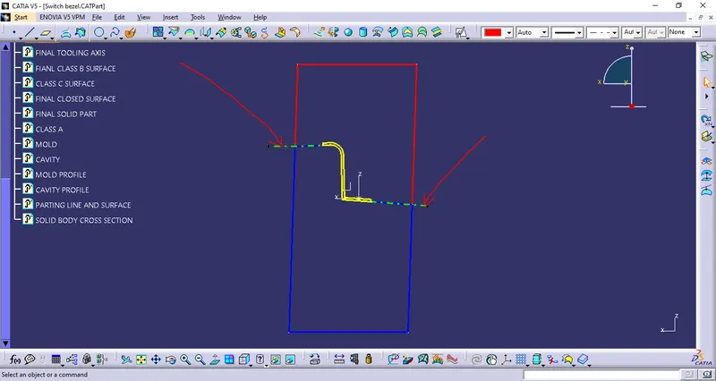
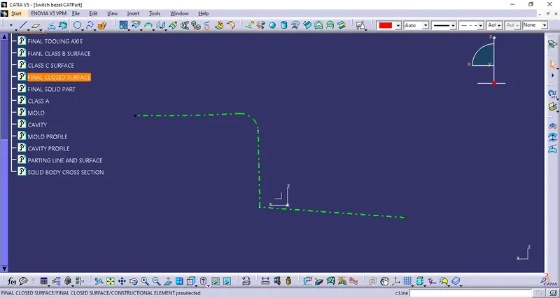
Mold and Cavity profile:
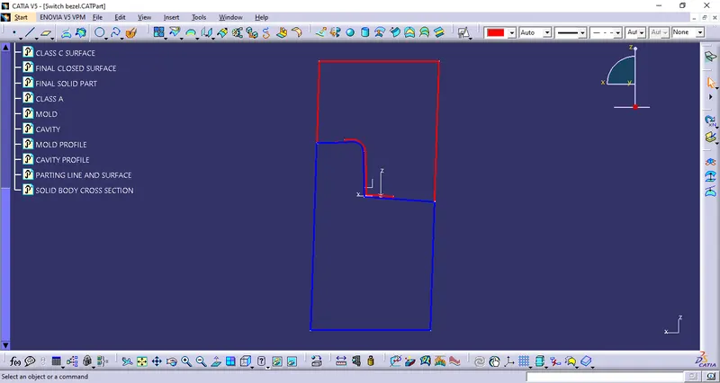
Parting surface:
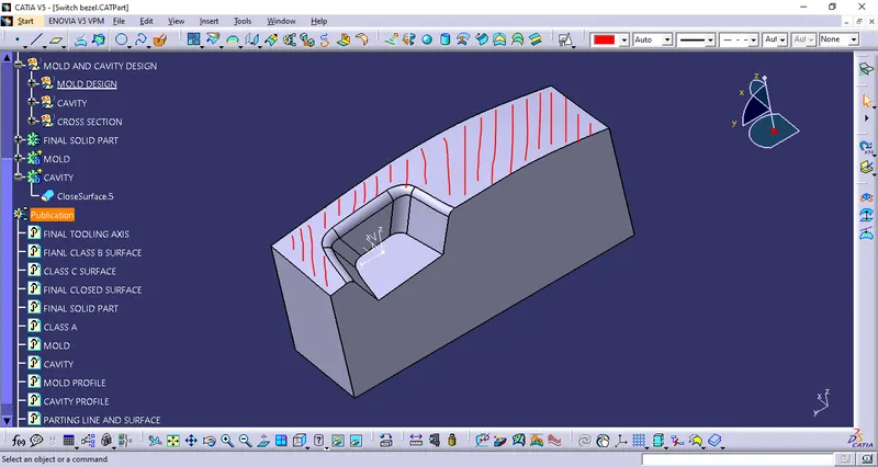
The parting surface is always made in accordance with the B surface. It is always made of the B surface.
Mold, Cavity and the solid part:
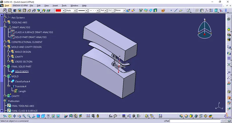
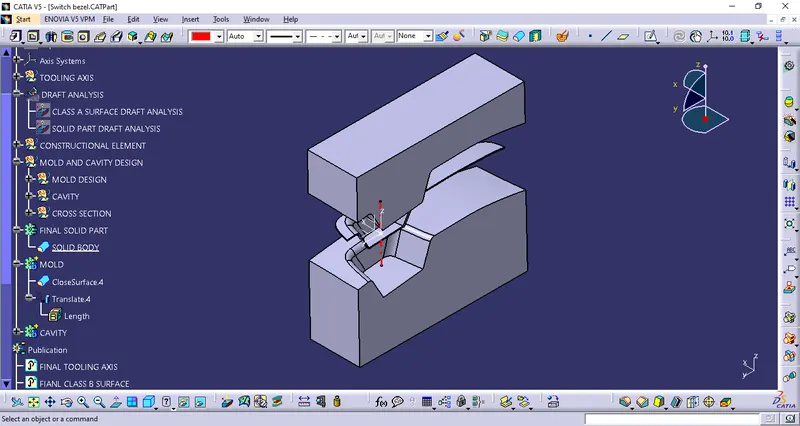
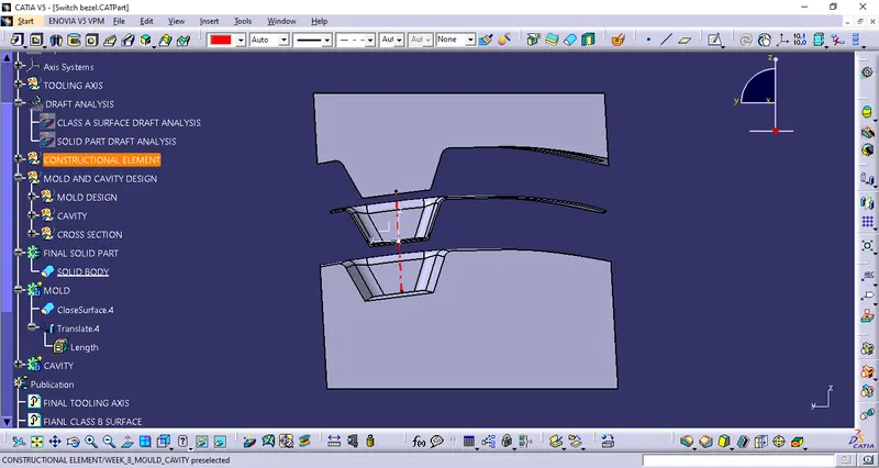
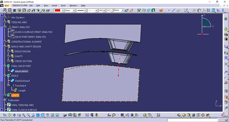
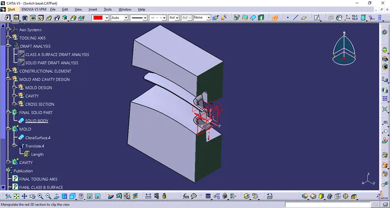
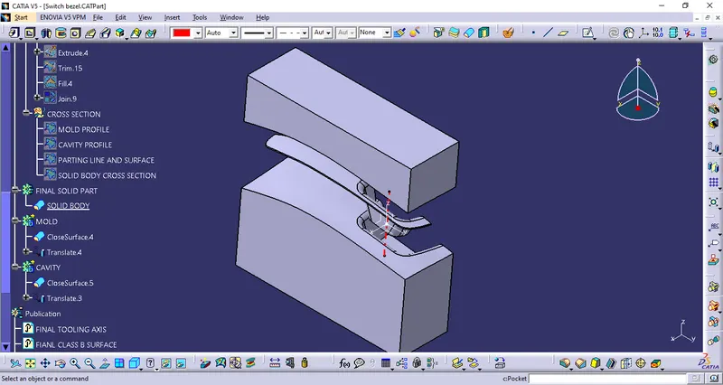
Feature tree for mold and cavity design