Week 8 - Challenge 5 - Core & Cavity Design
AIM:
Design the Core & Cavity blocks of switch bezel component.
OBJECTIVES:
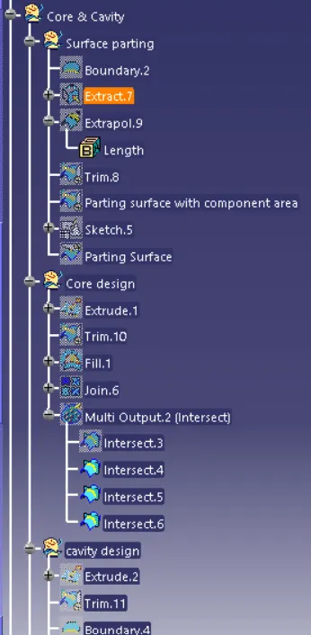
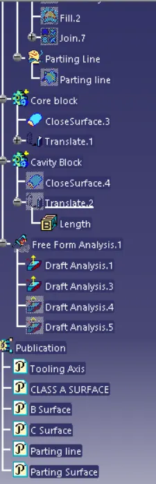
- Ensure proper tree structure
- All sketches should be created under geometrical set
- Closed surface feature should be used to make solid body from surface.
- Should Publish Tooling axis , Switch Bezel Solid / Surface body , Parting Line and parting surface.
PARTING SURFACE:
Generally injection mold has two major components : the movable halve fixed and the fixed halve , during the inection molding process, these two halves and pressed tightly from a sealed hollow to avoid the melt flow leakage and maintain certain holding pressure , the pressed surface are called parting surface ,usually parting surface are biggest projection outline of part.
Parting B surface design directly affects the product quality , ease of construction and operation of the injection mold , the mold design is one of key factors to sucess
DESIGN METHODLOGY:
CORE PART
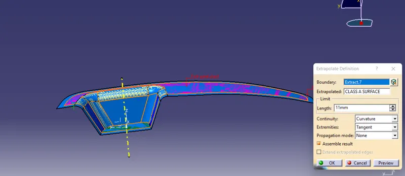
Extract the boundary from class A and extract the boundary .
Now using that extract extrapolate the surface with Class A as support
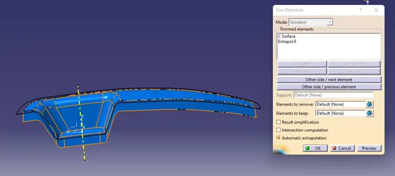
now trim extrapolated surface with class C to get inside portion.
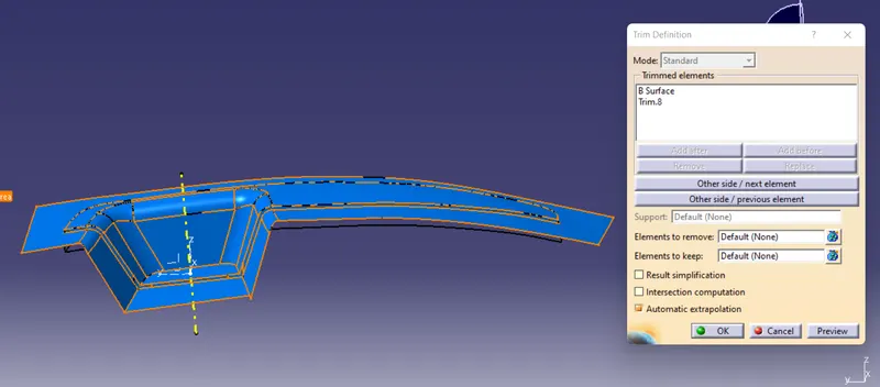
Now trim these trimmed surface with with B surface this gives parting surface with component area .
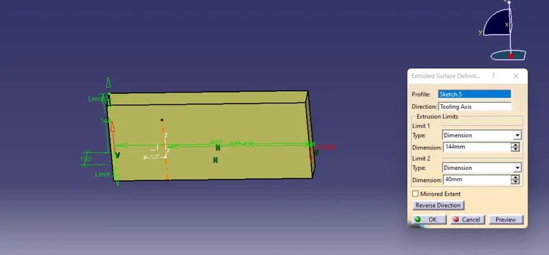
Now make a sketch to make and extrude overall trough tooling direction
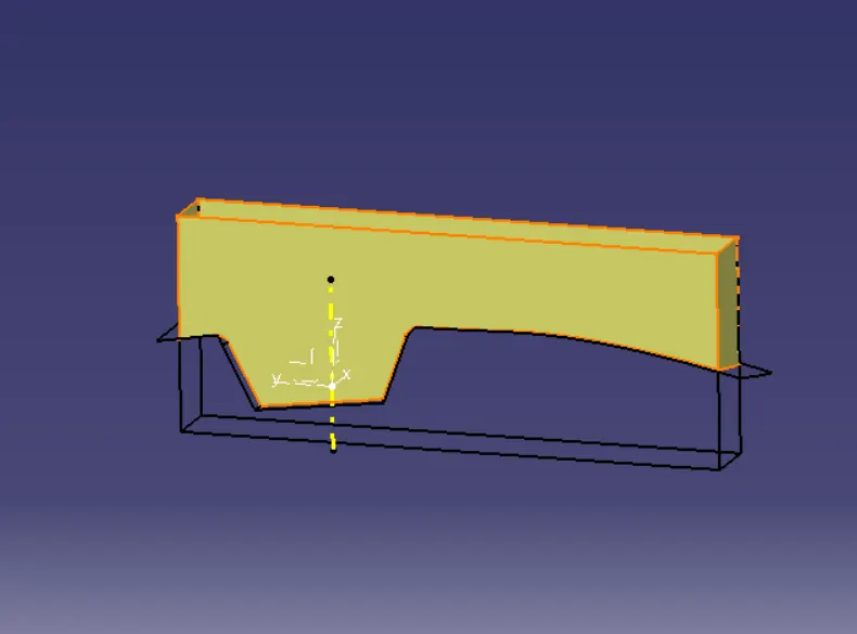
Now trim it with the parting surface with component area
Now fill the surface on the top and join both trimmed surface and fill surface thus it forms Core .
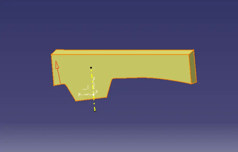
Now create a solid body using closed surface option.
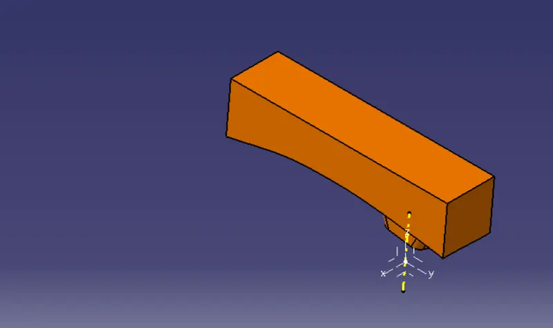
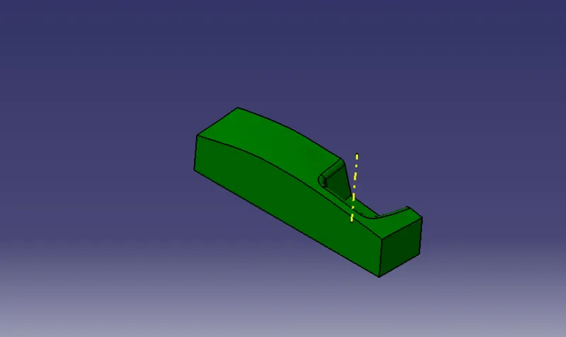
CAVITY PART
As above repeat the same process as core part and trim it on the other side surface
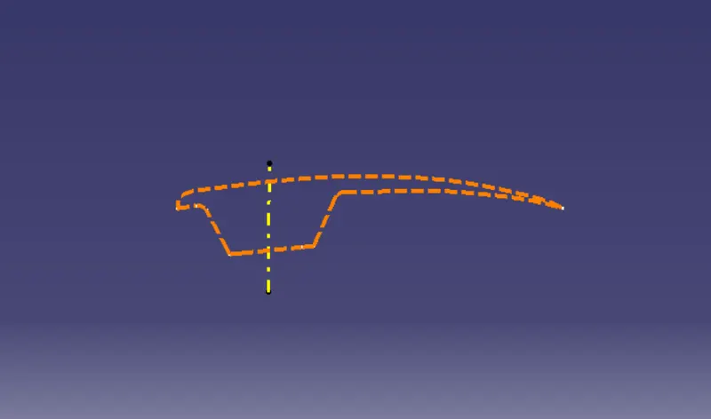
PARTING LINE
Take intersect option and take first element as class B surface and second element is trimmed surface of class A and class C Surface. this forms parting line.
Now trim the the parting surface with component area surface with parting line which gives us actual Parting Surface
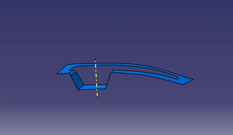
Different views
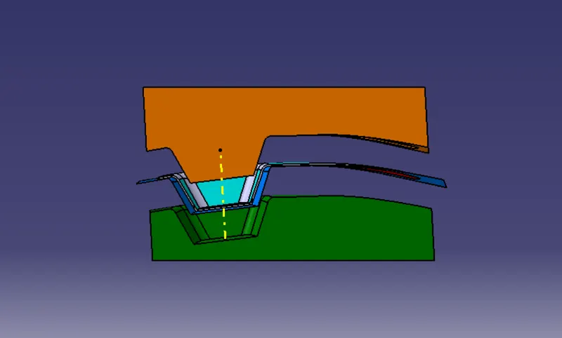
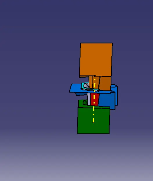
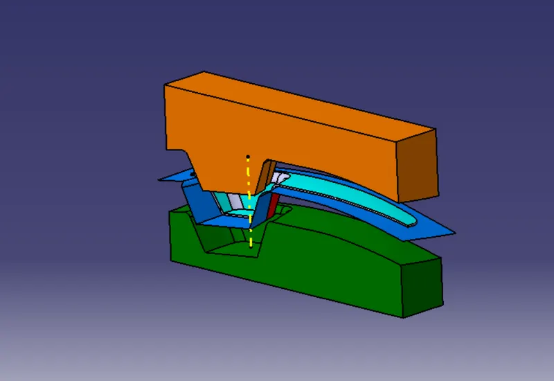
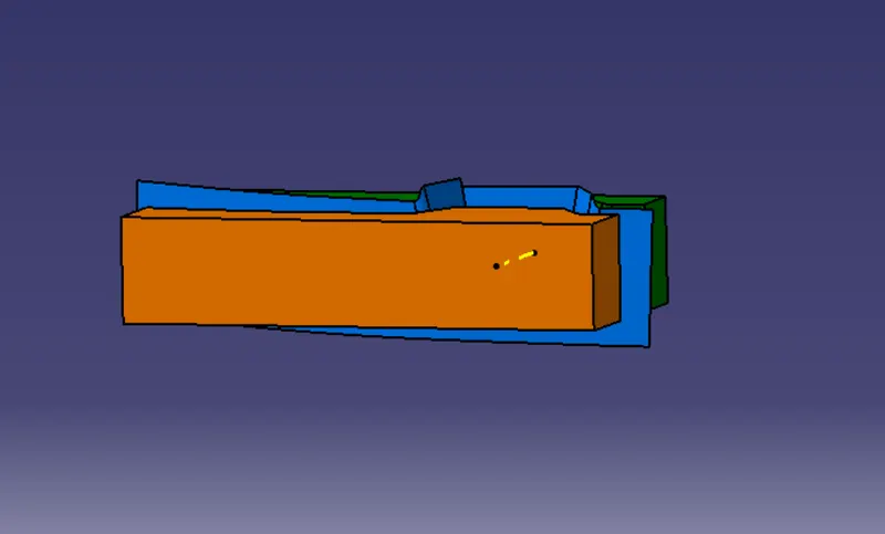
DRAFT ANALYSIS(Solid body):
To perform draft analysis on the model: Go to menu bar > Analysis > Feature Draft analysis. to give draft direction use the compass and align Z-axis of it with tooling axis. Once it properly aligned , lock the draft direction. A red point shown on the screen ,select class A-surface and it will show us the current of the model . then go to display tab on draft analysis and select the first option under it colour scale and it will show draft value .set the value to 3 deg under the colour scale variat and press ok.here analysis can be done in two ways quick analysis and full anaysis we choose quick analysis.
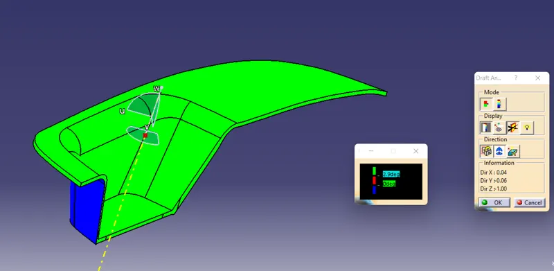
Here draft analysis shows
- The Green colour is drafted walls above 3 degree.
- The Red colour is drafted walls above 0 degree.
The analysis shows the drafted walls of Switch bezel are above the par of 3deg which is permissible to manfacture in injection modeling.
DRAFT ANALYSIS(Core & Cavity):
To perform draft analysis on the model: Go to menu bar > Analysis > Feature Draft analysis. to give draft direction use the compass and align Z-axis of it with tooling axis. Once it properly aligned , lock the draft direction. A red point shown on the screen ,select class A-surface and it will show us the current of the model . then go to display tab on draft analysis and select the first option under it colour scale and it will show draft value .set the value to 3 deg under the colour scale variat and press ok.here analysis can be done in two ways quick analysis and full anaysis we choose quick analysis.
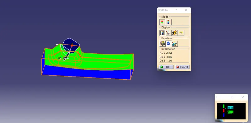
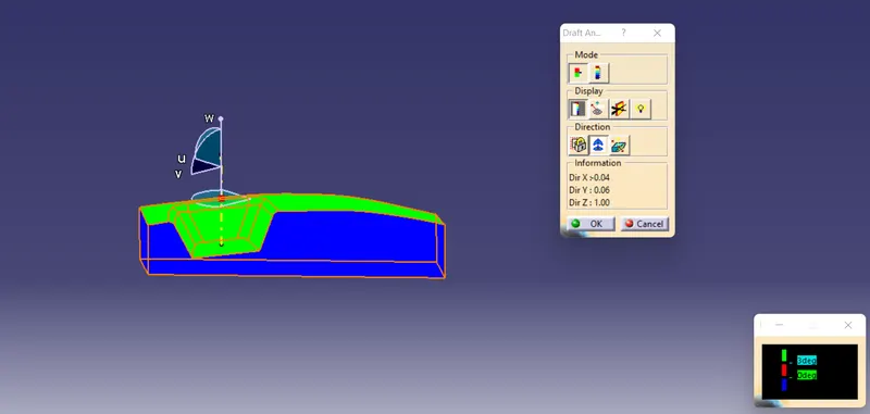
Here draft analysis shows
- The Green colour is drafted walls above 3 degree.
- The Red colour is drafted walls above 0 degree.
The analysis shows the drafted walls of Core & Cavity are above the par of 3deg which is permissible to manfacture.