Week 8 - Challenge 5 - Core & Cavity Design
Draft Analysis in Catia
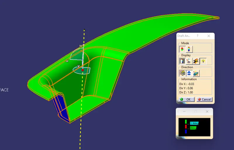
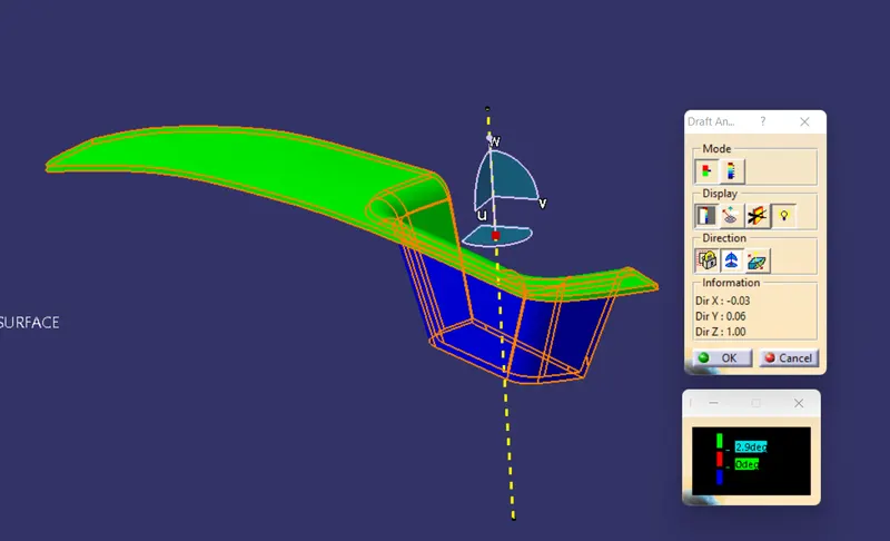
The Draft Analysis command enables you to detect if the part you drafted will be easily removed. This type of analysis is performed based on color ranges identifying zones on the analyzed element where the deviation from the draft direction at any point, corresponds to specified values.
so when we perform a draft analysis over a surface or on a component there will show 3 types of colour code, that is GREEN,RED and BLUE.
these three colours are corrospondes to the angle value present it that area.
If the colour is GREEN then the angle prensent in that are is 3 degree or mor than 3.
If the colour is RED then the surface having 0 to 3 degree andgle to the area.
If the colour is BLUE the the surface having the negative angle on that area.
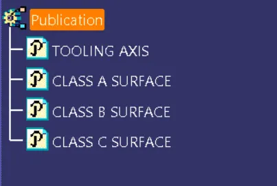
To perform draft analysis go to the surface workbench, switch view parameters in material mode, now unhide the tooling axis open draft analysis and adjust the compass with the dooling axis now click over the body and the draft analysis over the close body as shown bellow in the images.
CREATING CORE AND CAVITY
PARTING SURFACE
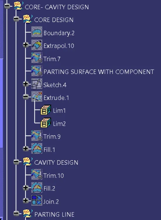
To create the parting surface bring the class B surface from the present in the tree structure trim it with join of the class AC curface, this is gona b Patring surface with componant.
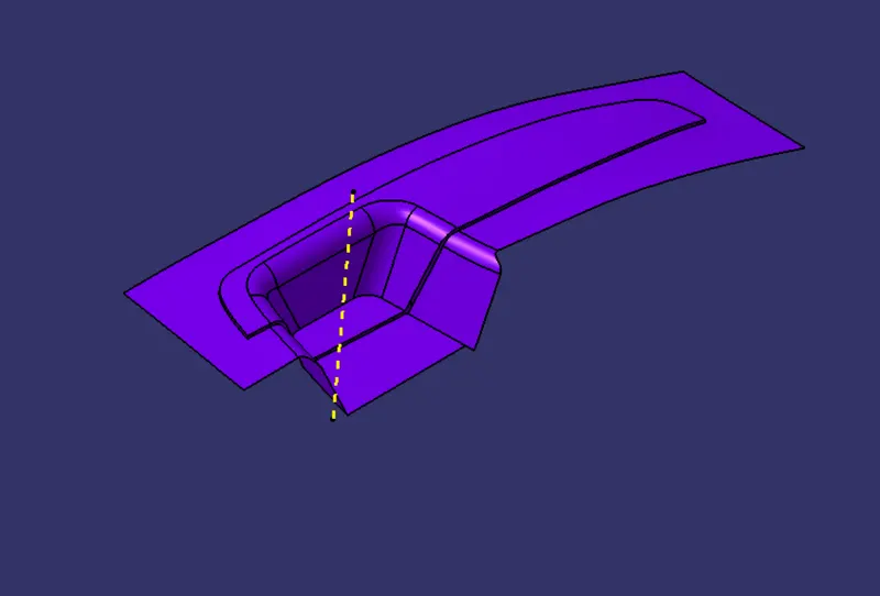
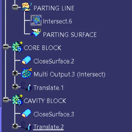
now create intersection with class C surface and use split command and split the surface from iside to create the parting surface.
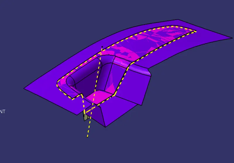
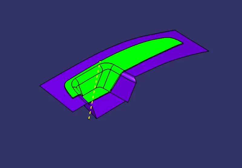
CORE
To create core use the parting surface with component first.
unhide the axis system which is at center of the component we created during the design of the switch bezel. sketch on the XY plane of the axis system which is perpendicular to the tooling axis. make sure that the sketch cover all the component area in it.
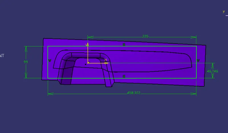
then extrude it upward in direction of tooling axis.
Trim it with the Parting surface with component surface fill its upper area using fill command and use close commad to make a solid in it.
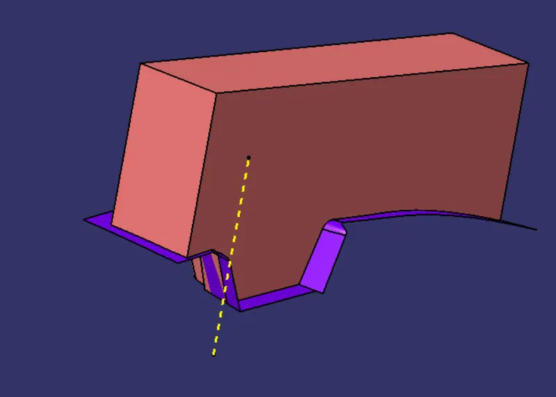
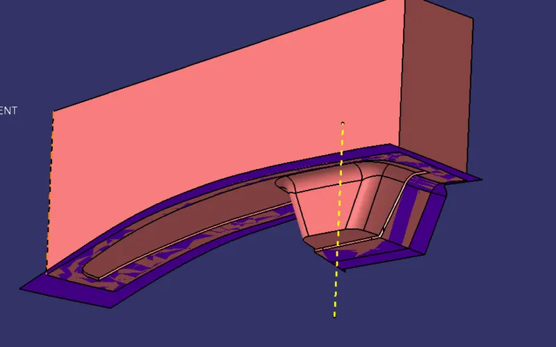
CAVITY
To create the cavity block first bring the Class B surface from the tree and then extrude the same sketch we extrude for the core block, in sdownside using tooling axis as Direction.
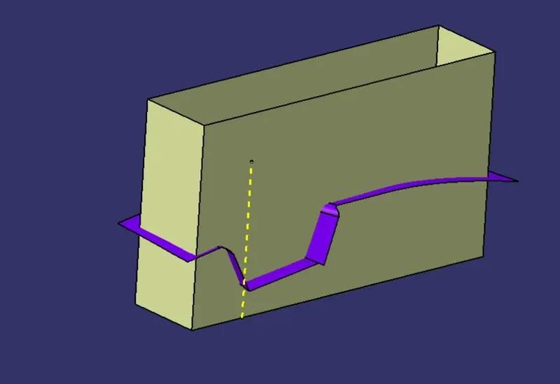
then trim thhe surface with class B surface.
same as the core fill the surface using fill comand and the. then solidify the surface using the close surface command in part design.
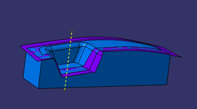
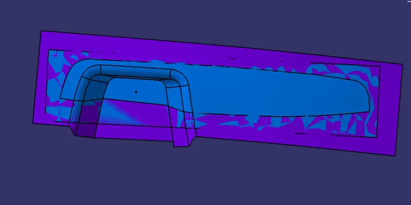
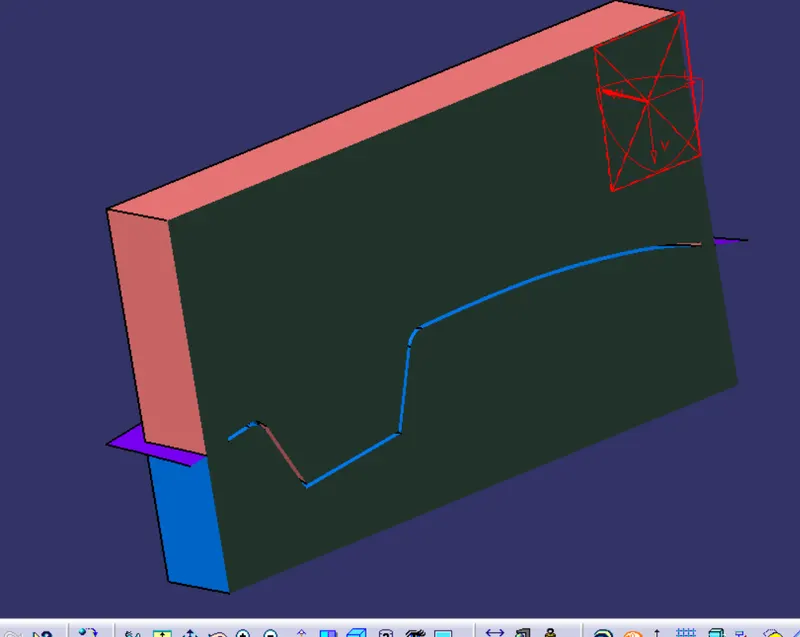
This ia the intersection line of all the surfaces
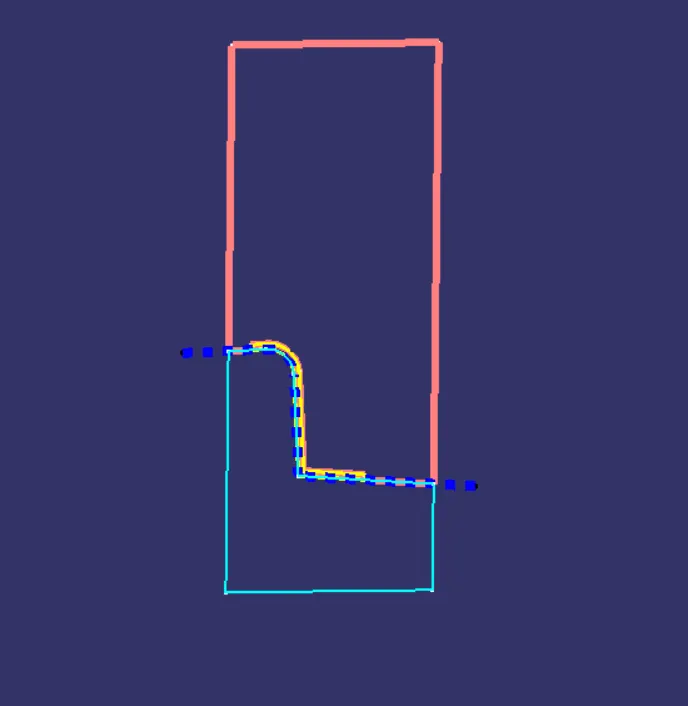
the one which is red colour is a intersection of the Core part
the one in Sian colour is intrsection of the Cavity part
the one in Blue is section line of the Pating surface
last onw in yellow is the section line of the component
Here is the dynamic section of the CORE and CAVITY
Dynamic sectioning with ZX plane
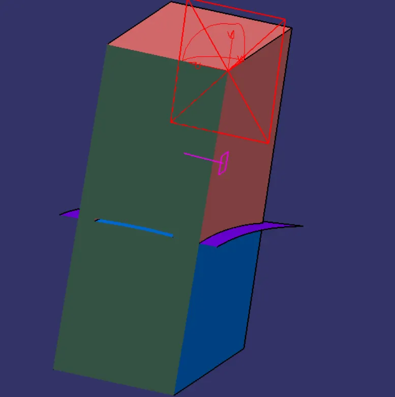
Dynami sectioning with YZ plane
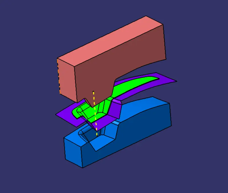
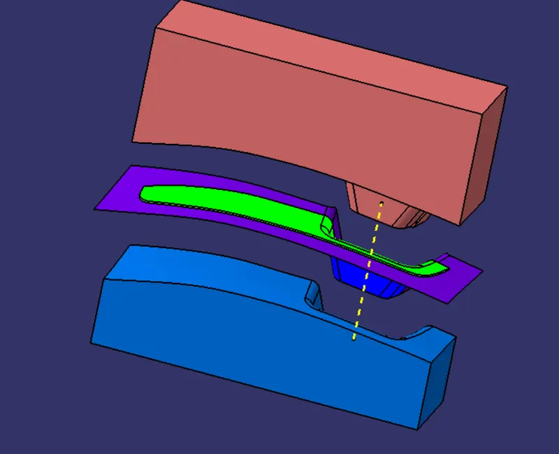
De- assembled View
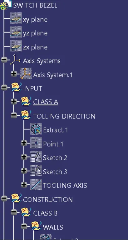
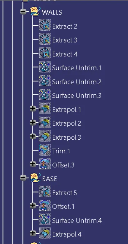
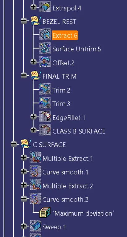
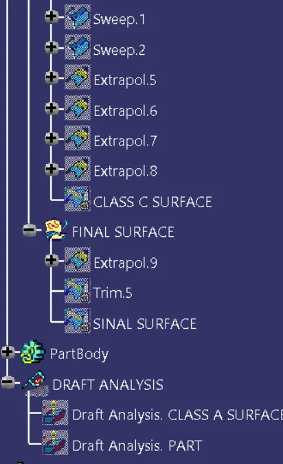
TREE STRUCTURE