Week 8 - Challenge 3 - Switch Bezel Design
Draft Analysis in Catia
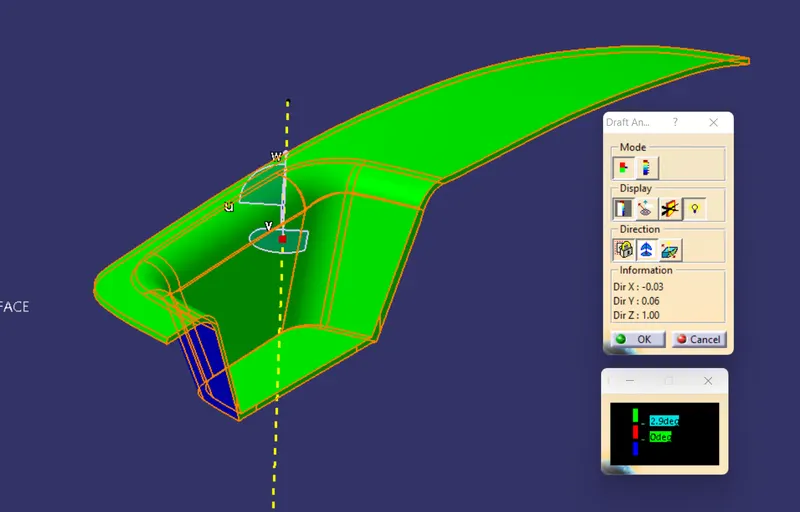
The Draft Analysis command enables you to detect if the part you drafted will be easily removed. This type of analysis is performed based on colour ranges identifying zones on the analized element where the deviation from the draft direction at any point, corresponds to specified values.
- There is a 3 colour code occured i.e Green, Red and Blue when we perform draft analysis on a surface or on a component.
- You can also modify the colour with correesonding specified value.
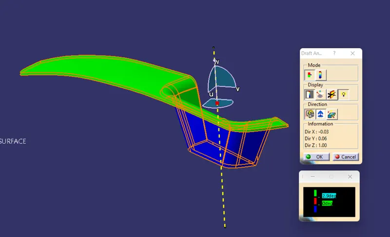
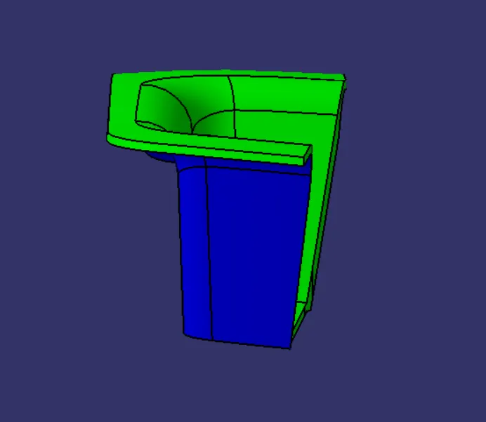
When it shows GREEN the draft angle present in that area is more than 3 degree. and green mean the componant is ready for tooling and manufacturing.
for example
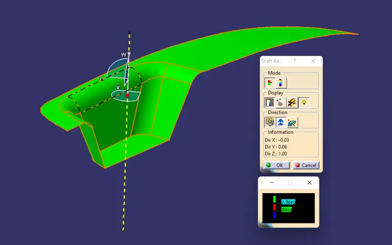
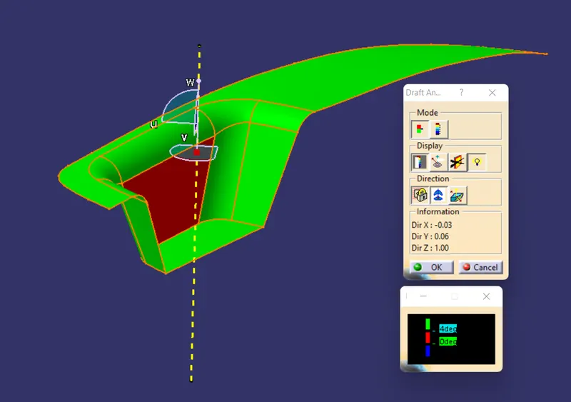
If the colour is in RED that mean the draft angle present in that are is between 0 to 3 dgree. so we have to modify it to make the componant ready for the manufacturing.
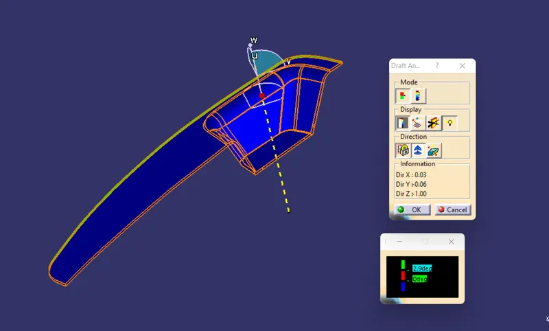
If the colour is BLUE, the engle prensent in that area is negative / less than 0 degree.
Creating a tooling axis with Bisecting Method
- Analise the surface so we can find the direction for the tooling axis so in this case it is Z.
- To create a tooling axis with bisecting method firstly create intersection line in X and Y direction.
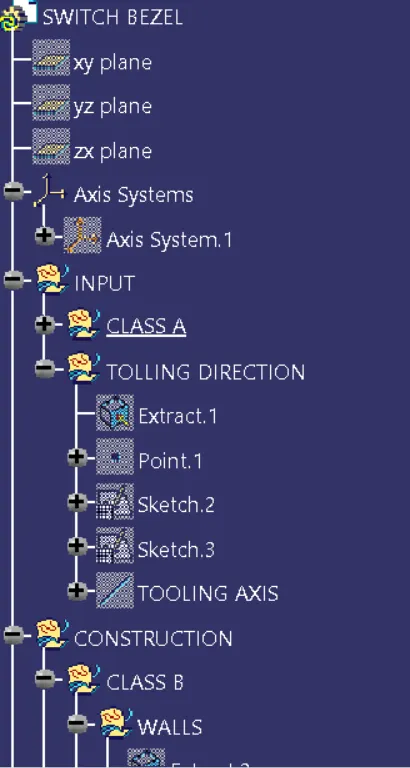
To create to the tooling axis or say tooling direction, extract the base surface of the class A surface and create point at centre of that extracted surface. Insert axis system on that point.
Now create intersection using position sketch in both X and Y direction.
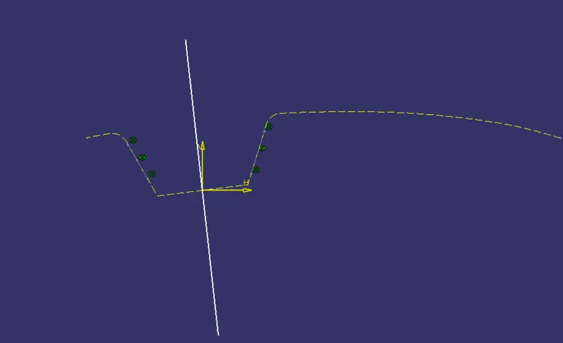
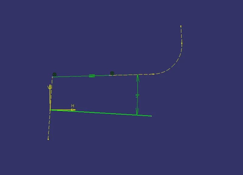
Create Bisect line in each X and Y direction sketch using that that point as a midpoint.
Bsectimg line in X direction
Bisecting line Y direction
Then create a bisect line using X and Y line and name it as Tooling axis.
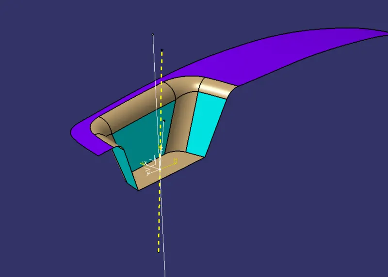
DRAFT ANALYSIS FOR CLASS A SURFACE
CLASS B SURFACE
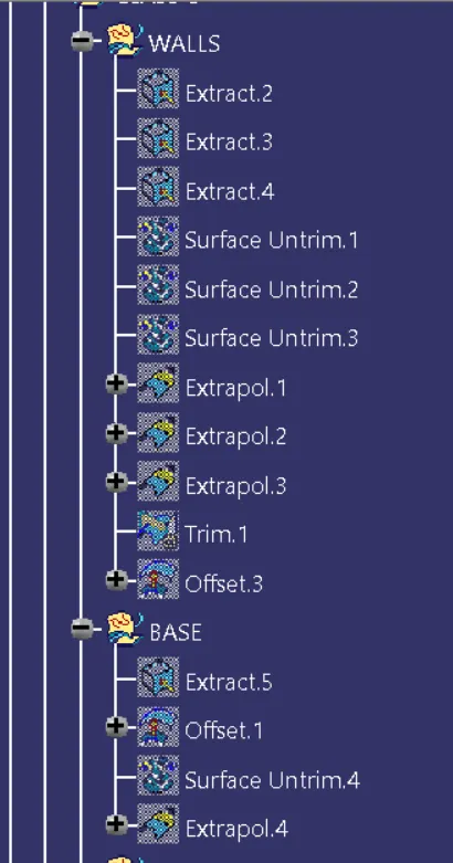
To create Class B surface extract the walls, base and switch bezel rest one by one.
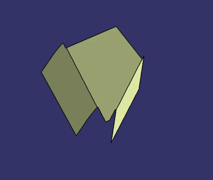
Wall – extract the 3 wall surfaces from class a surface, untrim them and extend them using extrapolate command to ensure these surfaces intersect each other. Now trim them with each other to get the appropriate shape of the surface. Now offset them 2.5mm outside of the surfaces.
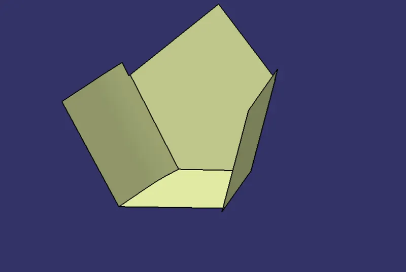
Base - same as the wall surface extract the base surface from class A , offset the surface 2.5 mm downside, untrim it and extrapolate so it can intersect with the wall surfaces. Next trim it with the wall surface to get required shape as Class A surface.
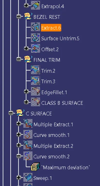
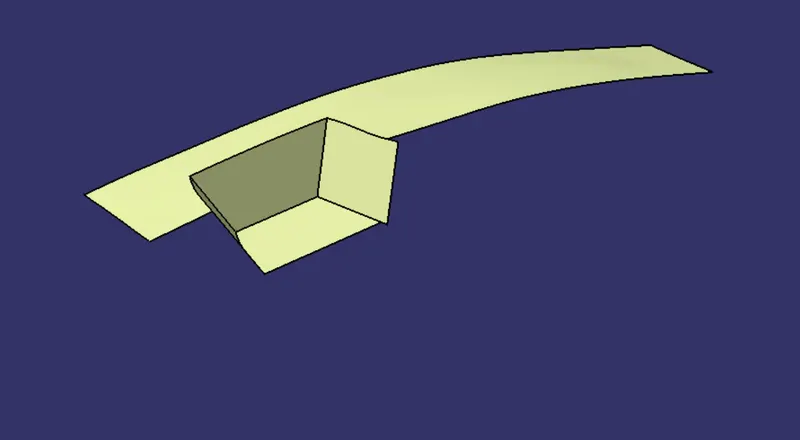
Switch Bezel rest surface - Extract the surface from class A surface, untrim the surface and offset it 2.5mm downside or say inside. Trim it with the walls to get the appropriate shape.
Applying fillets - applying fillets it’s a very important task in product because we need a uniform shape of fillet inside of the part with respect to the outside fillet. In this part the outside fillet is R 15mm so we have calculate the inside fillet value. Fillet value of the outside is 15mm and the thickness of the component is 2.5mm so fillet value minus the thickness e.i 15-2.5 its 12.5 .
12.5mm the Inside fillet radius. Apply to required edges.
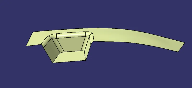
( Above image is the final ouptut of the Class B surfcae )
CLASS C SURFACE
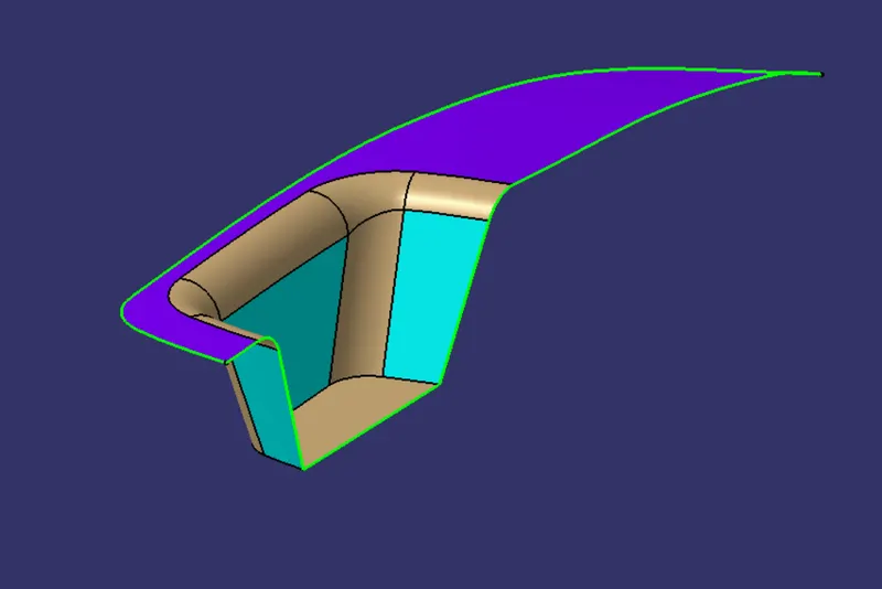
To create class c surface use boundary command over the Class A Surface to create the edges or create multi-extract command to extract edges separately. After extract use Curve smooth command to smoothen the curve around the class A surface to get an single curve, I will make the sweep easy.
the green lines are extrcted from the class a surface
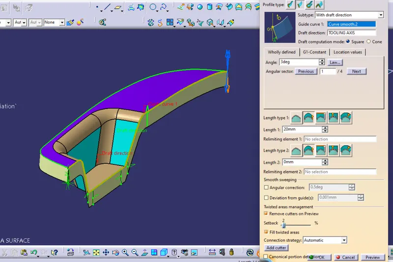
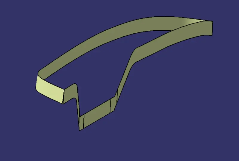
Use sweep command select draft with direction option and give angle of 3 degree and extend it an certain value so it is ale to intersect with B surface.
FINAL SURFACE CREATION
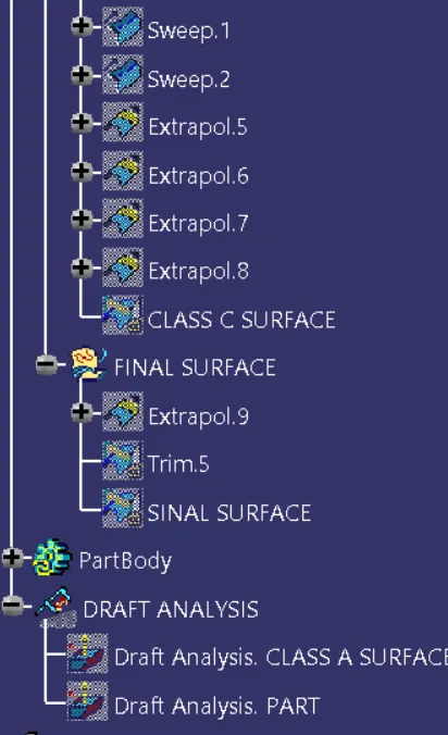
Join the Class A and Class C surface then trim it with Class B surface. Ensure isn’t have any open boundary using boundary command.
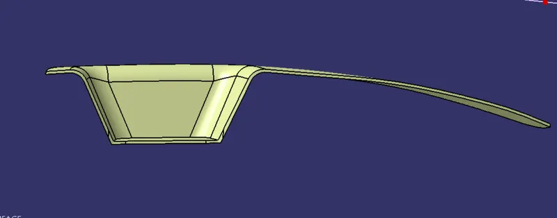
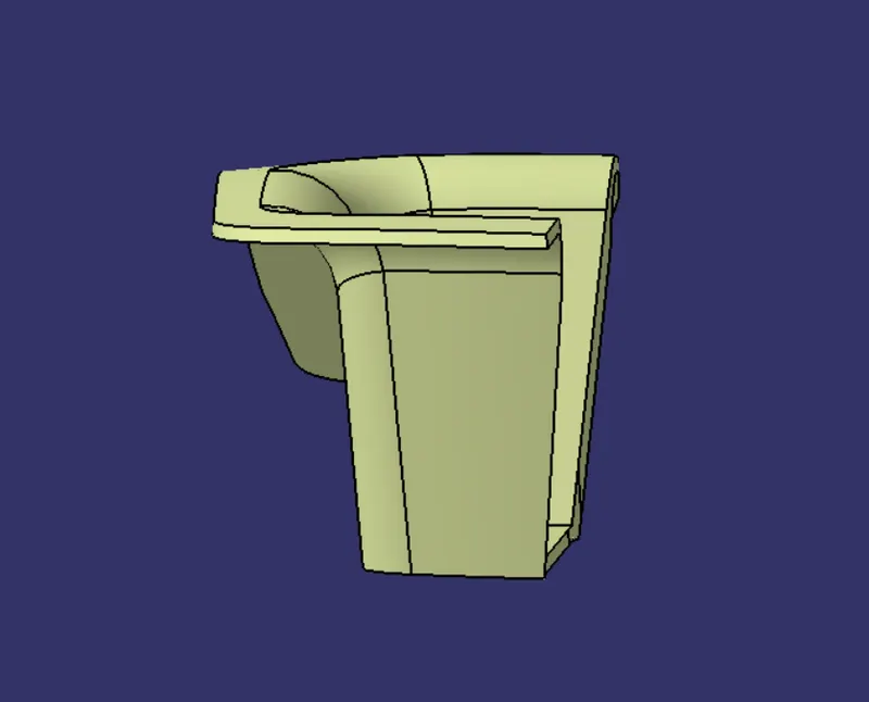
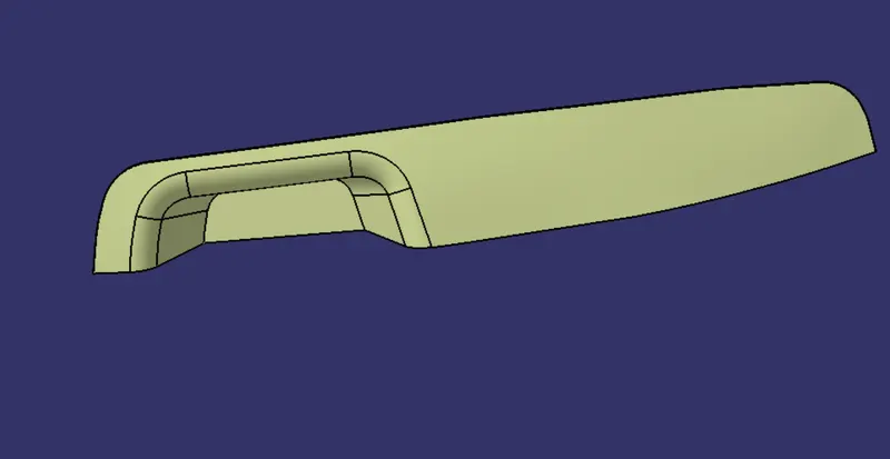
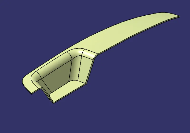
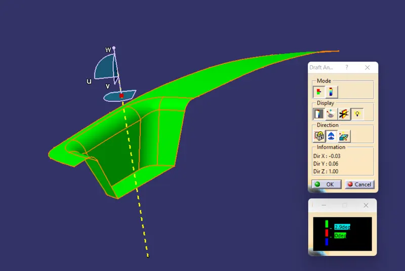
Now go to the part workbench and use close body command to create body inside the final surface and letter on perform draft analysis on the close body.
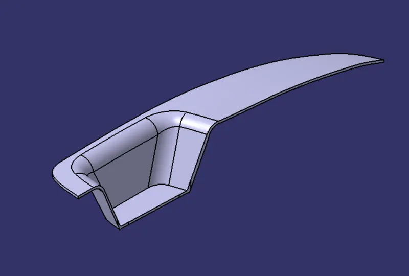
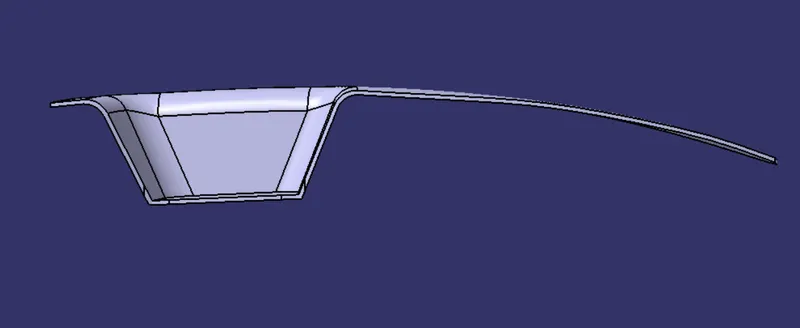
DRAFT ANALYSIS OF CLOSE BODY
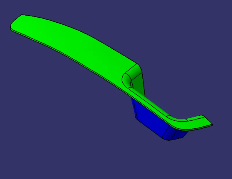
To perform draft analysis go to the surface workbench, switch view parameters in material mode, now unhide the tooling axis open draft analysis and adjust the compass with the dooling axis now click over the body and the draft analysis over the close body as shown bellow in the images
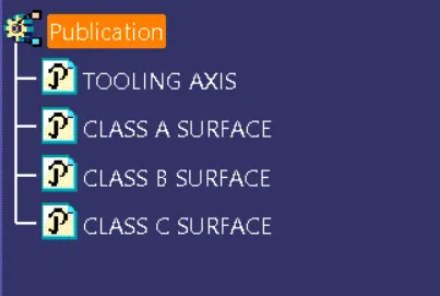
TREE STRUCTURE