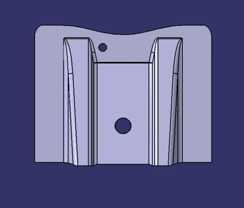
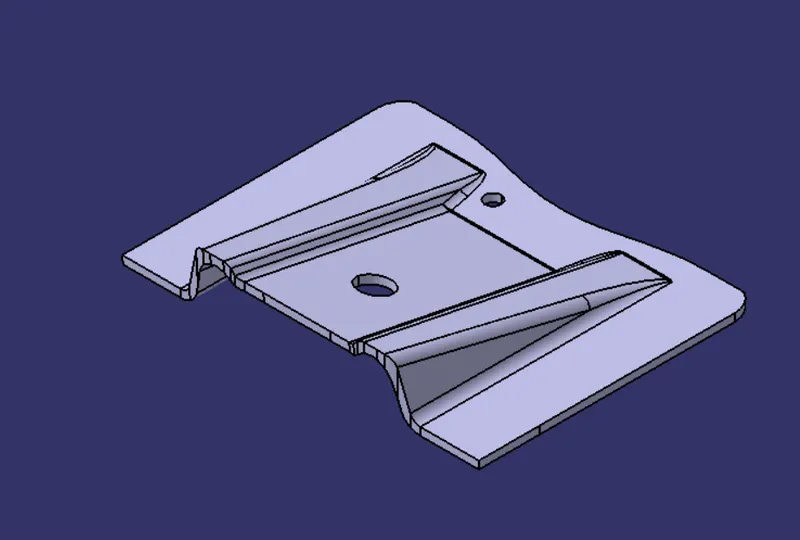
Week 8 - Challenge 2 - Base Bracket Design
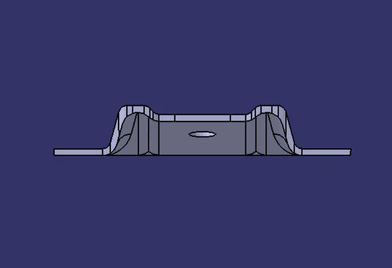
DRAFT ANAYLYS AND MODELING OF BRACE BRACKET USING SURFACE MODELING
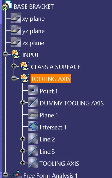
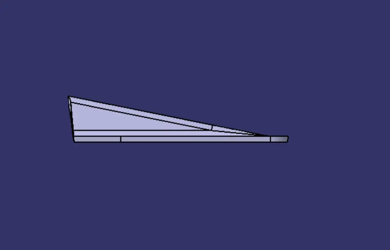
To crate a tooling axis by Bisecting Method
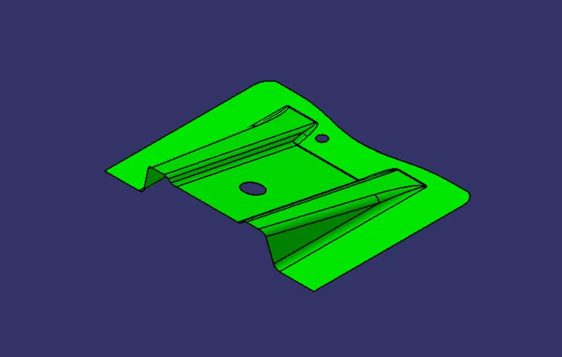
1. Analise the given class A surface for in which direction the tooling axis can we create.
2. Create an intersection using YZ plane. Find the surface line which will help to create center line for the tooling axis. Use line and extend these line in both side very well.
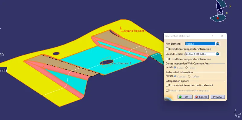
3. Again using the line command create a bisecting line using the both lines and the center point, name it as tooling direction.

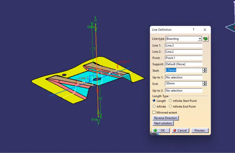
4.Change the tooling axis appearance so we can easily identify it.
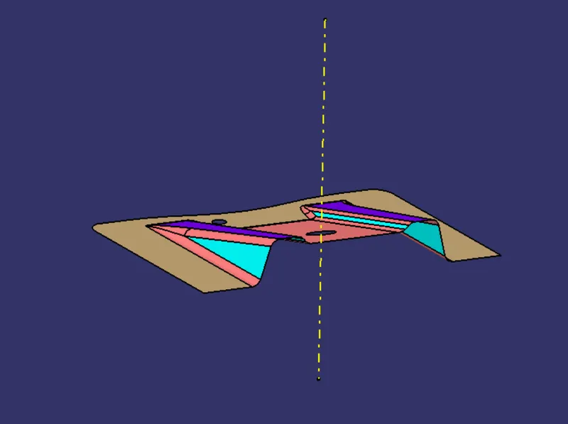
Draft analysis
To perform a draft analysis change the view parameters in material mode.
1. Now align the compass with tooling axis and lock the position.
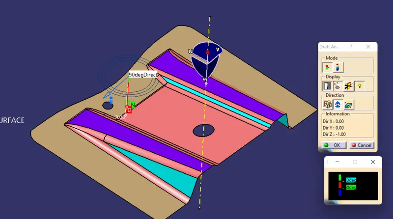
2. Click anywhere on the surface to see the surface is toolable or not.
3. There will be 3 color present on the surface when we perform the draft analysis. Green, red and blue.
4. These colors are the like the indicators for the drafts angle present on that surface.
5. If is GREEN the surface has no problem and ready for the tooling.
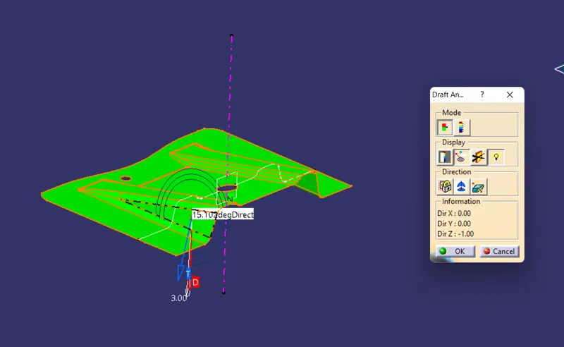
6 . If is shows RED then draft angle is more that the appropriate and for tooling, needs to modify the value of the angle so the part or product we are creating is toolable.
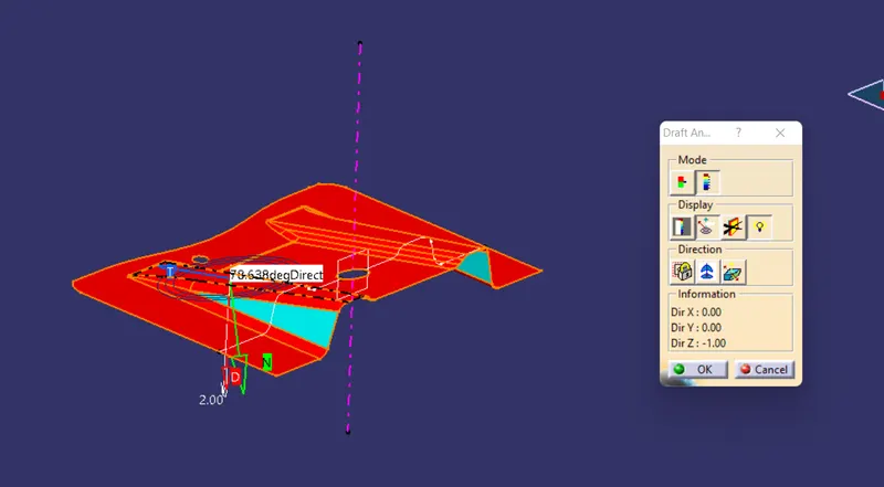
7. If is shows BLUE , the drafting angel is negative or less than 0 degree in the area.
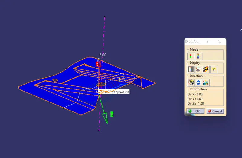
8. the widely acceptable drafting angle is 3 degree.
Creating B Surface
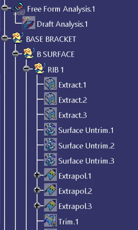
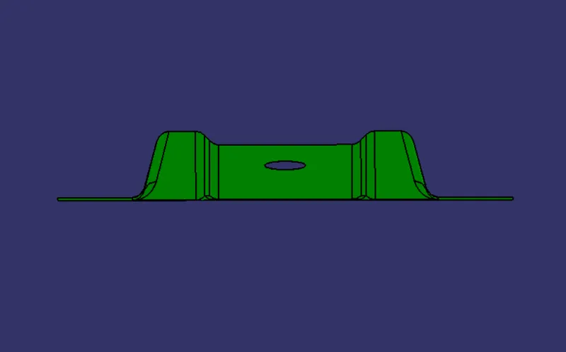
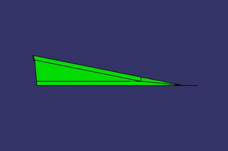
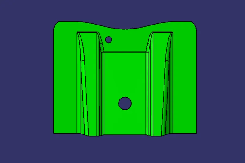
To create B surface extract surfaces from class A and take offset of a surface to inside of in the given thickness value, it this part It is 2.5mm so lets take offset of the surface 2.5mm to downside.
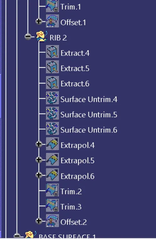
- Make ribs – extract the surface take offset of three surfaces which are joined together with the fillet. Untrim them and extrapolate them individually so the three surfaces intersect each other very well.
- Trim the three surface to attend the shape as the class A surface.
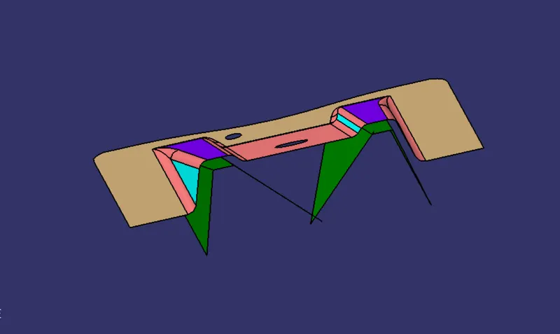
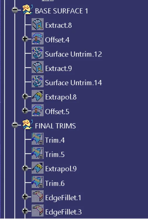
3. For base surface 1 – extract the base 1 surface take offset 2.5mm downside.
4. Untrim the surface using untrim option.
5. Extend the surface using extrapolate so it will intersect with the surfaces of both the ribes
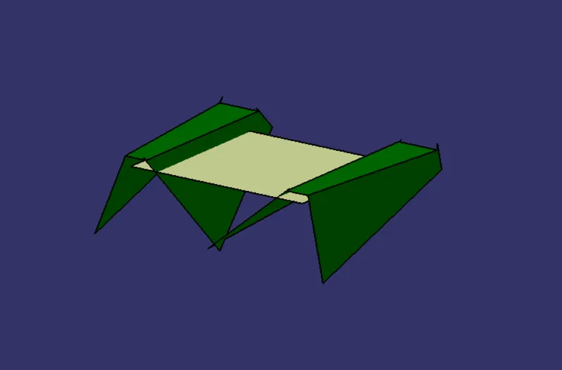
6. Trim the base 1 surface with ribs to get a proper shape as class a surface.
Craete a Main Base Surface
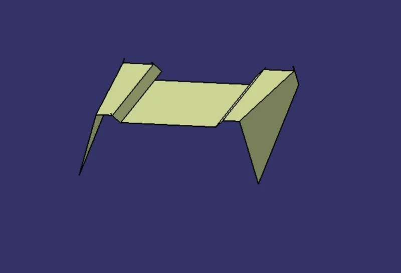
1.Same as before extraxt the base surface from the Class A, offset it 2.5mm.
2. Untrim the surface, extend it by using Extrapolate.
3. Trim the surface with the ribes.
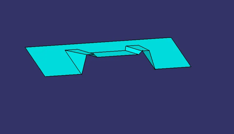
Now apply fillets, applying fillets is importang whenever we work on the surface taking offset from the Class A surface.
1. in this surface their is a 3mm radius fillet is applied in wvery fillet resent in the class a surface, and we took offset of 2.5mm inside from the upper surface that is Class A surafce.
2. So we have to claculte the fillet value for the B surface that is , tha fillet value present in the class A surface pluse given thicknes of the part or componant that is 2.25mm, the offset which we took during creation of the B surface is the thickness. so the fillet value for the B surface is 3mm + 2.5mm that is 5.5 mm.
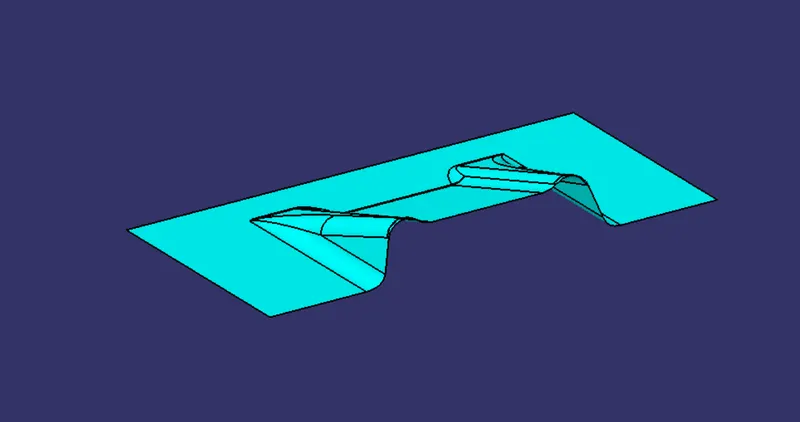
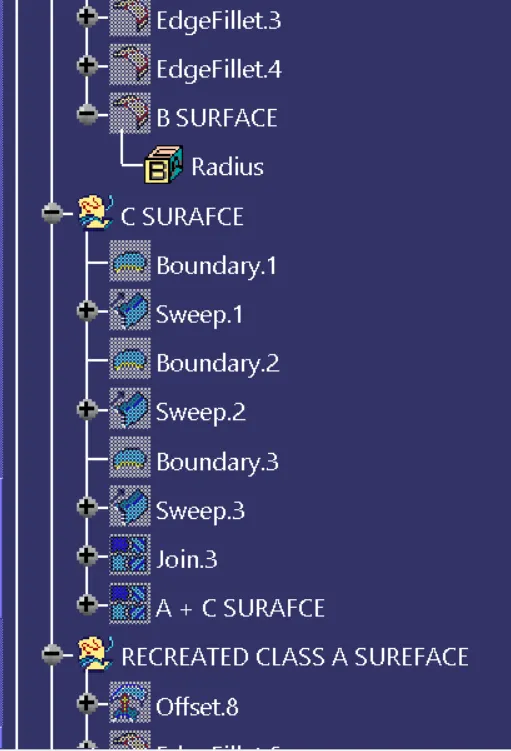
C Surface Creation
1 . To create C surace create a outer boundary of Class A surface.
2. Use sweep command to create C surface give the dranft angle 3 degree using tooling axis as a draft direction, given in the following image
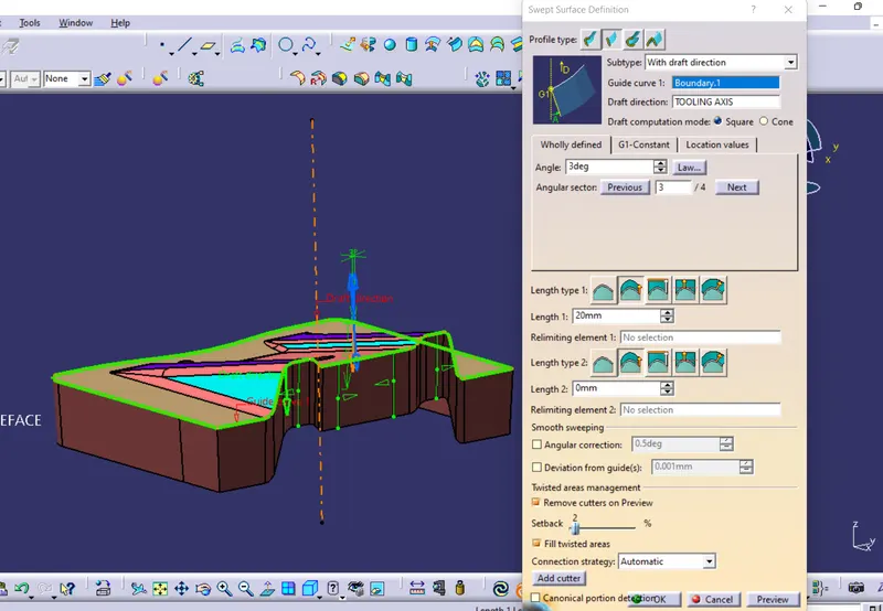
3. do same for the two holes over the surfce
Now using join command join the A and C surface
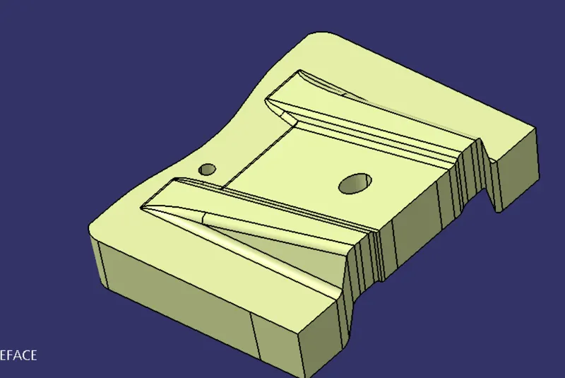
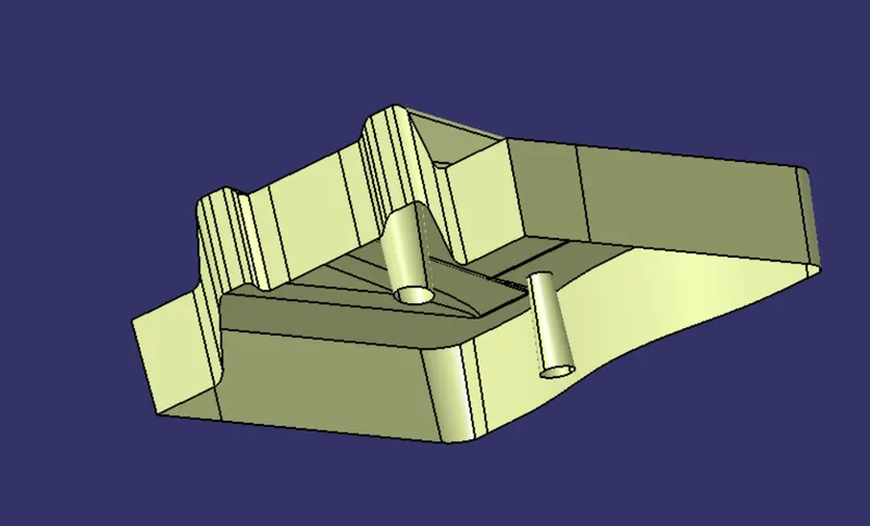
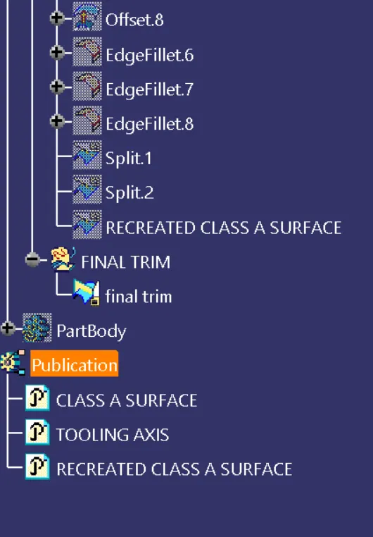
Now its time for the final trim
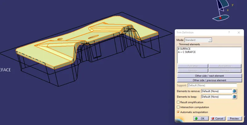
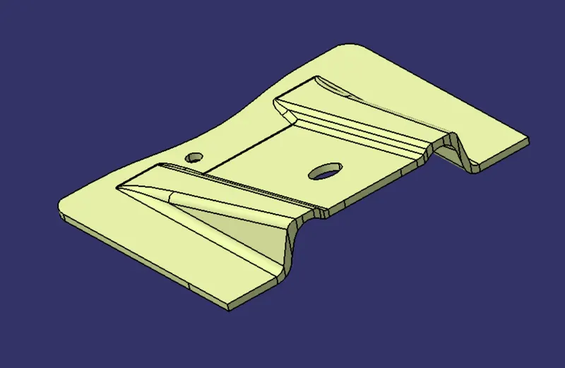
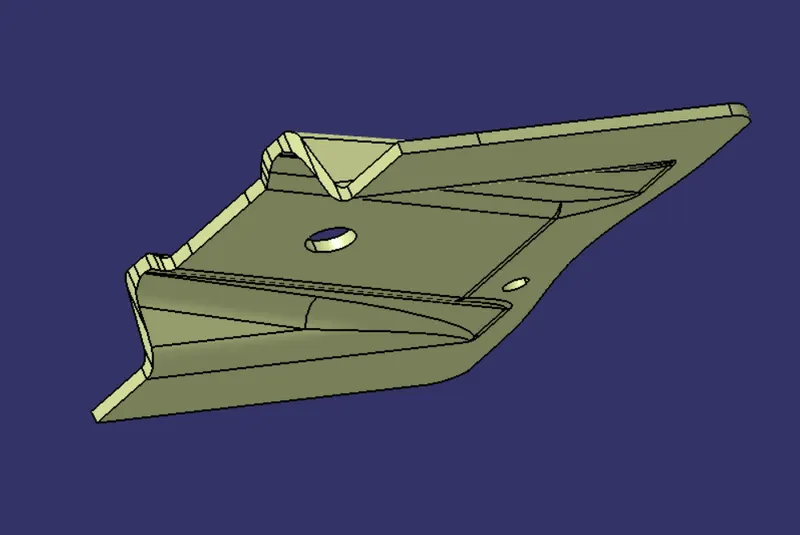
Trim the A and C surface using B surface and vise versa to get our closed surface for Part body.
TREE SRUCTURE