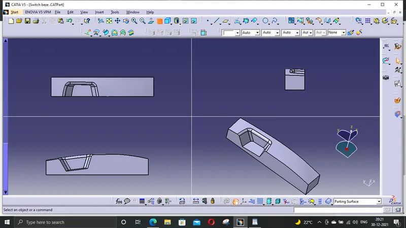
Week 8 - Challenge 5 - Core & Cavity Design
Given Class A Surface
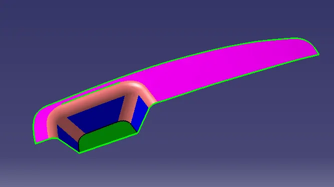
Procedure To Creat A Tooling Axis
First The given class A surface is imported to the catia v5 software.
By using boundary option the suface is checked for any discotunity(Can also done by using join option).
A dummy Tooling Axis was created to give a better visualisation about the possible tooling axis.
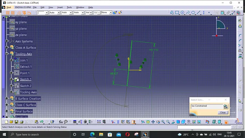
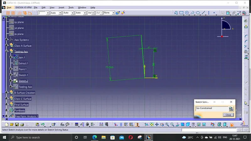
By using axis system and intersecting comand two different intersect are created through using XZ &YZ planes Respectivly.
Then the lines are extended using point to point line command and then an axis was created for each intersect separetly using bisecting line comand.
Then the toling Axis was created with respect to the both the axises created.
Publication
The tooling axis and the Class A surface are publishied for furter easy referance.Tool->Publication
Performing Draft Analysis
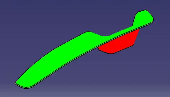
Insert->Analysis->Feature Draft Analysis
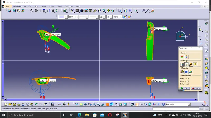
Draft analysis was carried out by placeing the compass over the tooling axis And locked to a specific direction.
If the surface is green then it passes the requirements or else further operation needed to be carried out.
Core Block
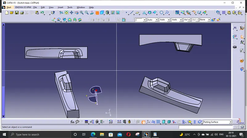
Cavity Block