Week 8 - Challenge 5 - Core & Cavity Design
CORE AND CAVITY DESIGN FOR SWITCH BEZEL
Objective
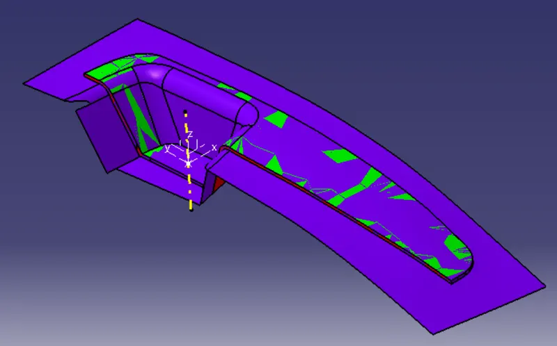
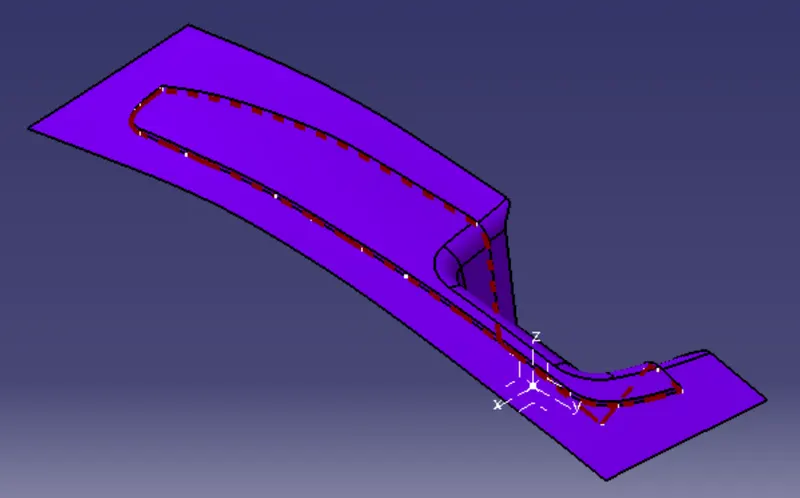
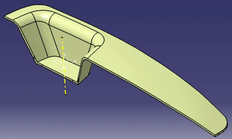
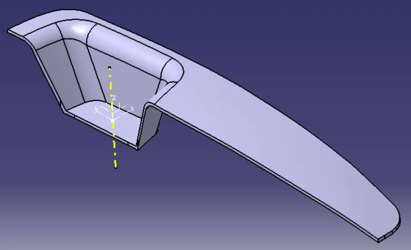
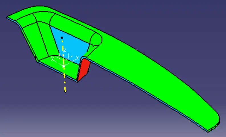
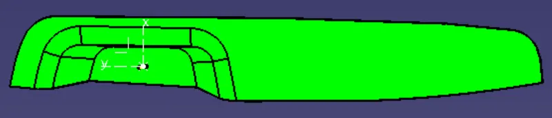
The main objective is to create design Tooling axis, Class-B surface and Class-c surface from given Class-A surface , solid model from surfaces, Draft analysis and also create Core and cavity blocks for the Switch Bezel.
TOOLING AXIS
It is defined as the the direction in which mould opens or core and cavity opens.
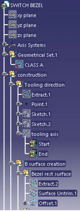
Steps
1. Check the gaps between the class A surface by using join and boundary operation.
2. Check the Class-A surface in all direction which is suited for tooling direction.
3. Extract the base surface make point on the center of the surface and provide axis system.
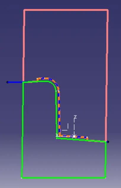
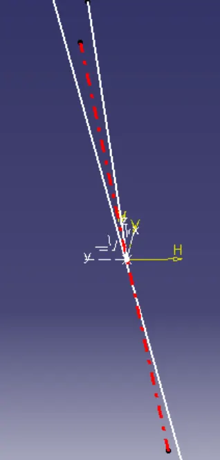
4. Use sketch command on YZ axis and create the intersect then draw two line on the intersect and make bisect line and exit sketch.
5. Use sketch command on XZ axis and create the intersect then draw line on the intersect and draw another line from point make 3 degree angle with lines.
6. Using line command selecting bisecting and selected the two bisecting lines and center point to get the tooling axis.
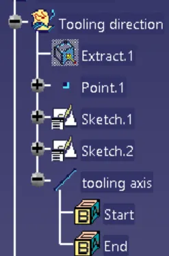
For Create Class-B surface
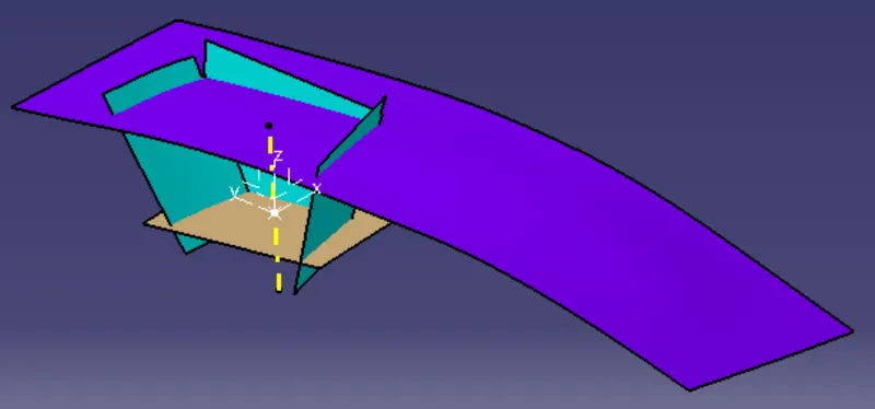
7. First work on Switch bezel rest surface, Use extract command used to extract from Class A surface.
8. Untrim the extract surfaces after that offset the surface to 3mm downward direction to the Class-A surface make it in a geometrical set.
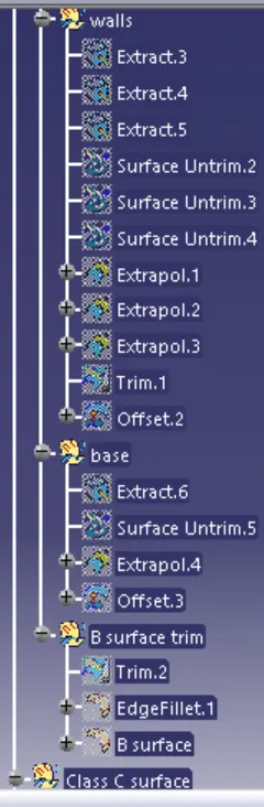
9. Next work on the walls, using the command extract, untrim, and extrapolate the wall surfaces.
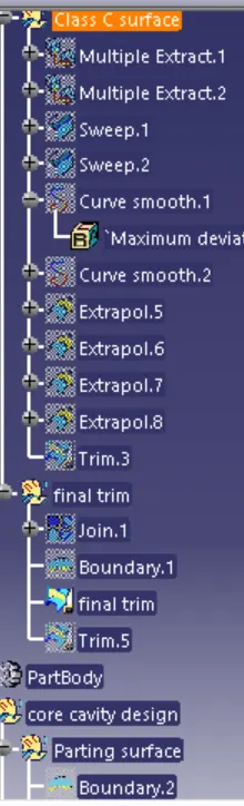
10. Final trim is done to the wall surface and offset to 3mm make it in a geometrical set.
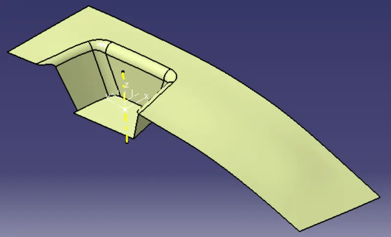
11. Next work on the Base surface, using the command extract, untrim, and extrapolate.
12. Final trim is done by selecting base, walls and switch bezel rest.
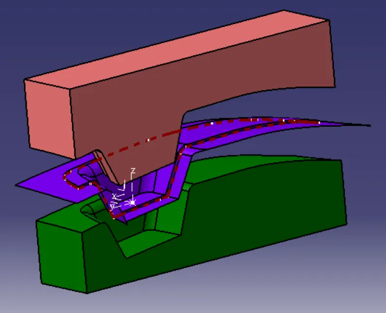
13. Provide edge fillet of 11mm and 12mm on the surface.
For Create Class- C surface
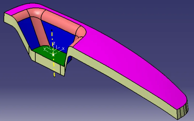
14. Unhide the Class-A surface, extract the boundary of surface and sweep
15. Use curve smooth command to smooth the boundary and replace it.
16. Use join command select the sweep surfaces and the extracted Class-A surface.
17. Final trim with Class-A surface and Class-B surface to get the Class-C surface
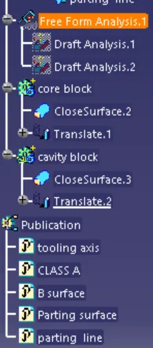
18. In part modeling select the close surface command use convert to soild model and draft analysis of the final plastic component of Switch Bezel.
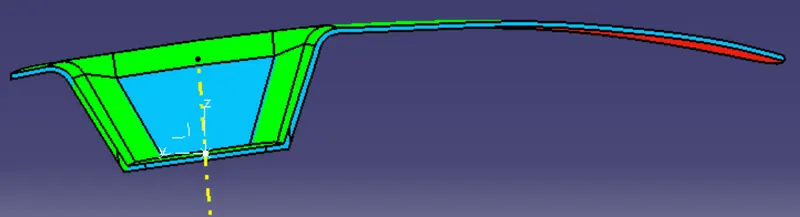
CORE AND CAVITY DESIGN
Core and cavity design is a stand-alone product that determines the ability of a component to be manufactured thanks to technological criteria (Moldability). This product allows also the user to fill up technological holes within the core and cavity surfaces, identify the parting lines and to generate the parting surfaces.
19. Create the parting surface make boundary of the class-A surface and extrapolate and trim with class-A and Class-B surfaces.
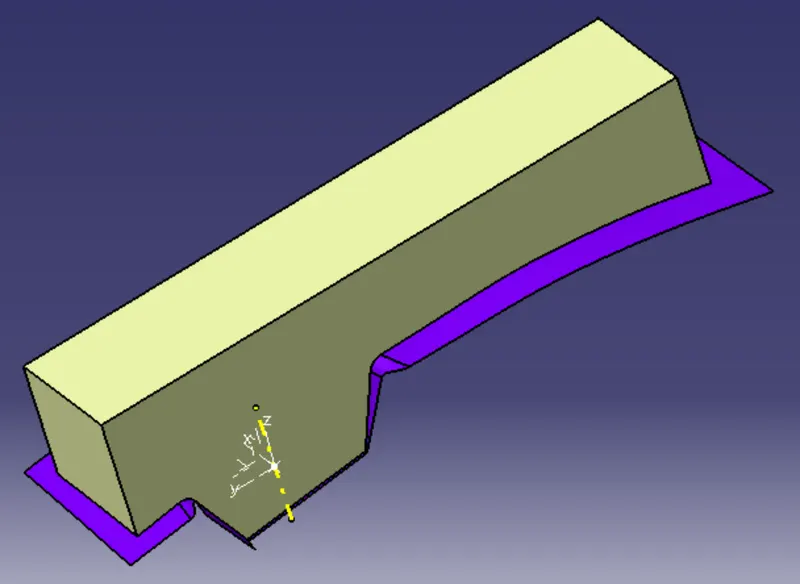
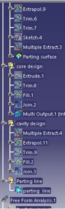
20. Create the core block by Sketch rectanglur box on XY axis and extrude then trim with the Parting surface.
21. Use fill command to fill the top surface and join with the trim surface then make the surface as close surface in part design.
22. Make intersection of the core block, Component and Parting surface.
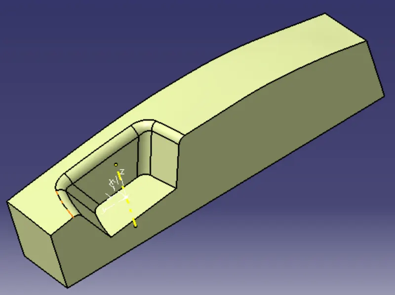
23. Create the cavity block trim with the extrude surface and class-B surface.
24. Use fill command to fill the bottom surface and join with the trim surface then make the surface as close surface in part design.
25. Make intersection of the cavity block and Create parting line by intersection by class-B surface and class-C surface then Transition to the core and cavity design.