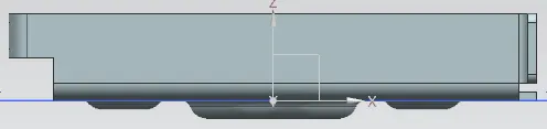
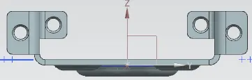
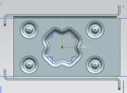
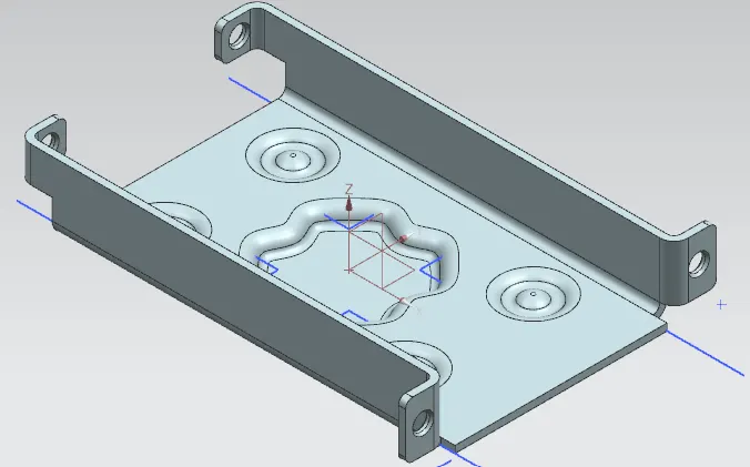
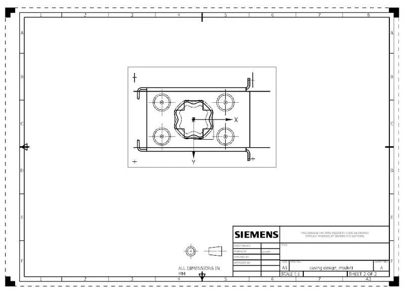
Advanced Sheet Metal Design Using NX Cad Challenge_1_Casing Design
DESIGNING A CASING USING NX CAD
Objectives
The report contains a detailed explanation of sheet Metal Design of Casing. The main objective of this course is to learn Sheet metal modeling, and also exploring most of the basic tools in NX Cad
INTRODUCTION
Sheet metal Design is the process of making thin sheet metal into different forms done by the of NX cad software. This helps to know how to use the basic type of sketch tool, Bends, Corners, Punches, Forms, Features in NX Cad.
Methodology
- Tab
- Normal Cutout
- Bend
- Flange
- Break corner
- Unbend
- Dimple
- Bead
- Mirror
- Rebend
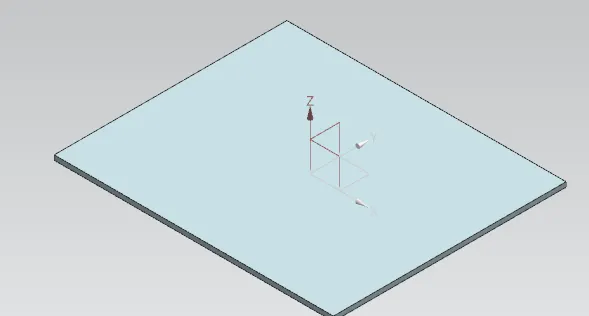
Tab
Tab is the Base feature or the exiting sketch or section.
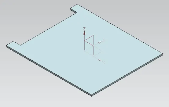
Normal Cutout
Normal Cutout command extract volumes from sheet metal by using sheet metal production principles. Cutting faces will be perpendicular to the sheet metal.
Bend
Bend command is used for bend from the base feature along a line. 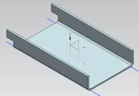
Flange
This command is used for extruding a sketch along a specified vector to form a base feature.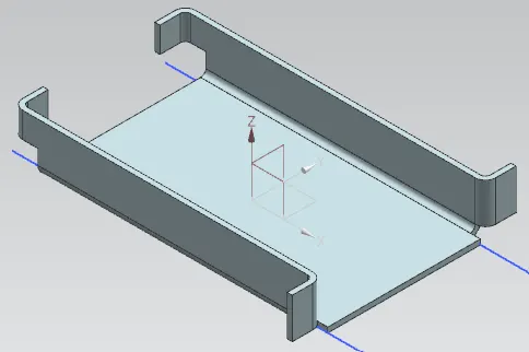
Break corner
This command is used to fillet or chamfer the sharp corners of a tab or flange. 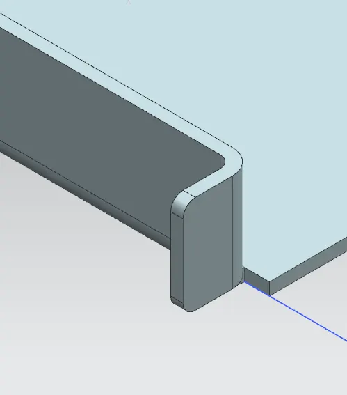
Unbend
This command is used to unbend the adjacent bends and flatten them back to tab 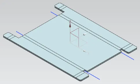
Dimple
This command is used to form a small deformation as per the sketch. 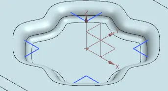
Bead
It is used for giving strength to the sheet metal. 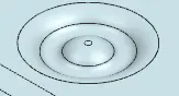
Mirror
This command is used to mirror a feature across a plane. here the features such as beads were mirrored using this tool.
Rebend
This command is used for re bend the sheet metal.
Conclusion
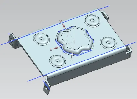
This being the first design in NX Cad gave me an insight the use of basic features like flange, tab, break corner, normal cutout, flange, dimple, unbend, rebend, and mirror.