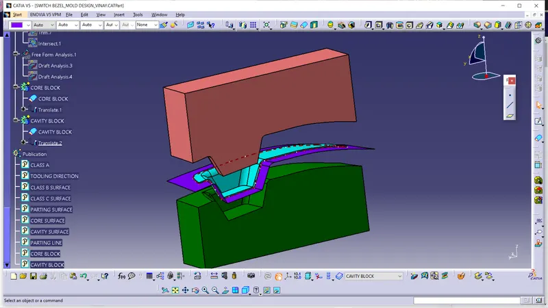
Week 8 - Challenge 5 - Core & Cavity Design
Draft analysis of switch bezel CLASS A SURFACE:-
We got the CLASS A SURFACE of the switch bezel to check the draft analysis and creating the thicken part body from it. Before checking or starting the procedure for draft analysis we need to check the surface. Initially we check the gaps between the surface and also check the no. of surfaces we have because, we need just one single joined surface for draft analysis. If the gaps were found then we will join the surface.
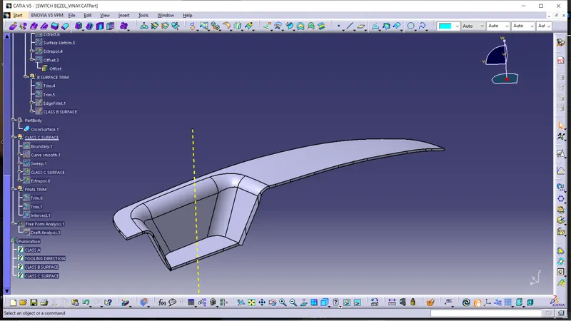
Initially we check the tooling direction by visually observing the part or surface. After calculating or finding the no. of possibilities than we start the draft analysis according the cheapest and best way to do the manufacturing by avoiding side cores and easy manufacturability for the part or surface creation. The draft angle can be 0.5 degrees to 1 degree. But, we used the 1.3degrees for better manufacturability and some less draft angled surface.
Initially we create a point for center or tooling direction creation. Then we create axis system by using that point with reference to main axis system. Now, we create the intersection line on the surface by using of ZY plane or coordinates. Then we draw line with using point to point feature on the lines which we have doubts for not clearing of tooling direction. Then we draw vertical bisecting line by using these two lines and center point which we were created. This will be “TOOLING DIRECTION” of the switch bezel.
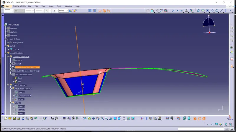
Then we created the dummy tooling direction by using the zx plane. But, here we don’t have the two lines for creating the bisecting line. So, we assumed another line from the center with 3 degrees angle with intersecting line of CLASS A SURFACE with zx plane.
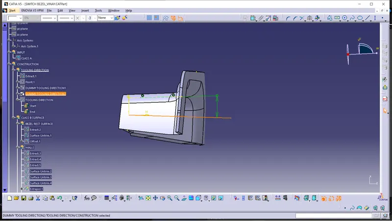
Then we created the bisecting line by using both dummy tooling directions and point which we created for the sketching. This bisecting line will be our “TOOLING DIRECTION” for the material.
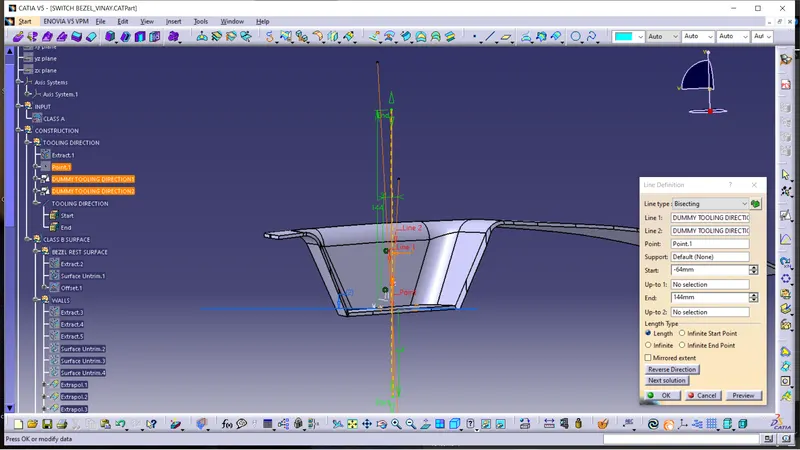
Tooling direction:-
Draft analysis:-
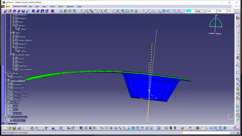
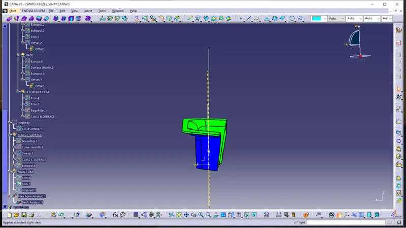
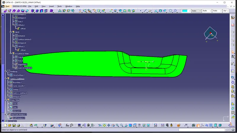
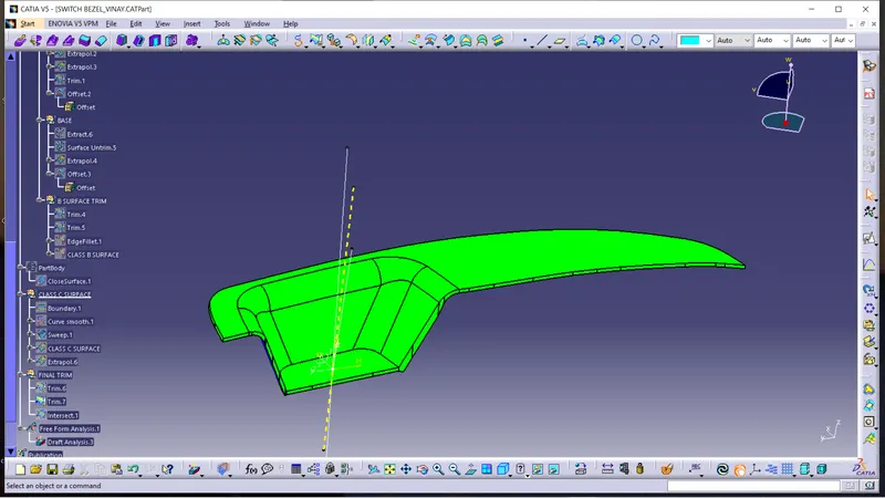
parting surface:-
parting is the surface which divides the core and cavity block while joining them together.
parting surface created by using the CLASS A, CLASS B & CLASS C surfaceS intially. That we mentioned as parting surface with combine part. we used that for creating the core block.
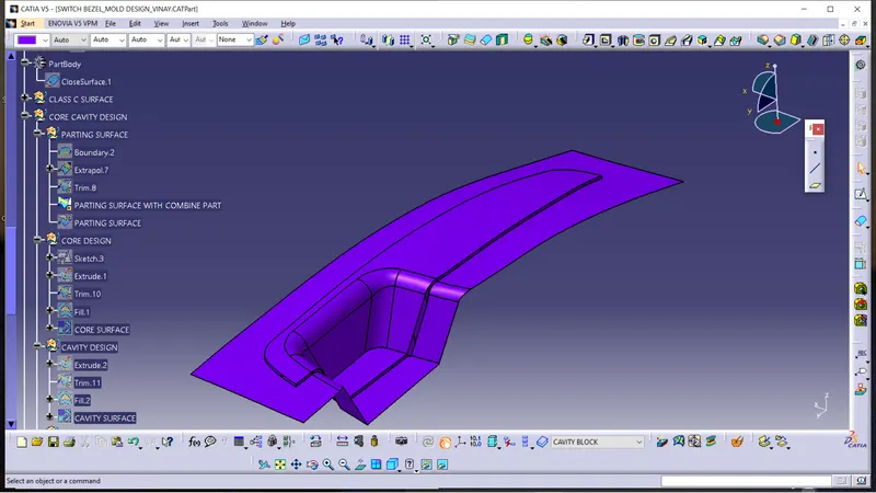
then we created the parting line which made by using theintersection of the CLASS B SURFACE and CLASS C SURFACE of the switch bezel.(brown dotted line is the PARTING LINE)
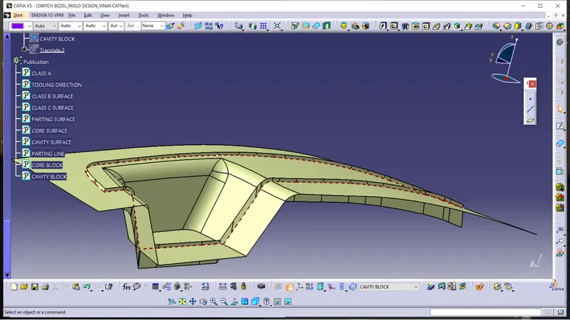
Then we trimmed the surface by using the parting line. this surface will be our PARTING SURFACE.
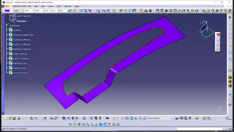
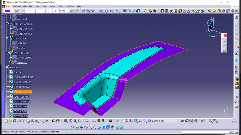
CORE BLOCK:-
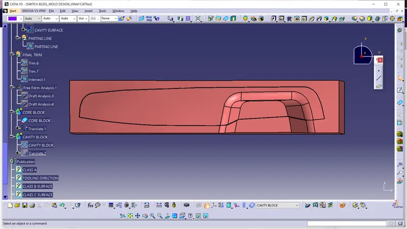
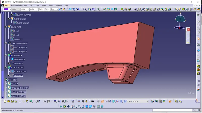
Core block is creted by using the parting surface with combine part and extruded rectangle by using the tooling direction. we trimmed the both combined. Then created the closed surface, this closed surface is our CORE BLOCK.
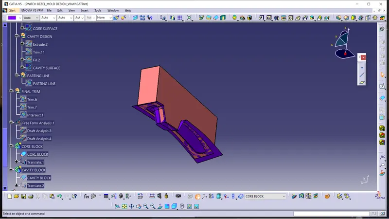
views of core block:-
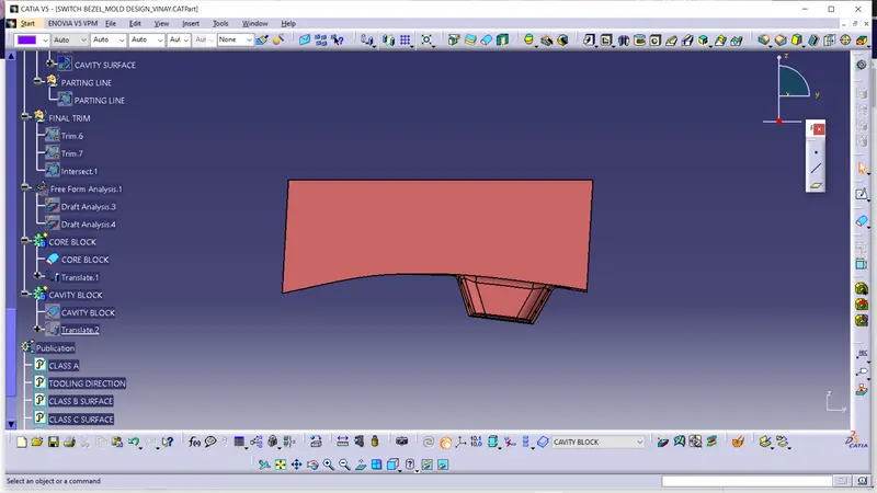
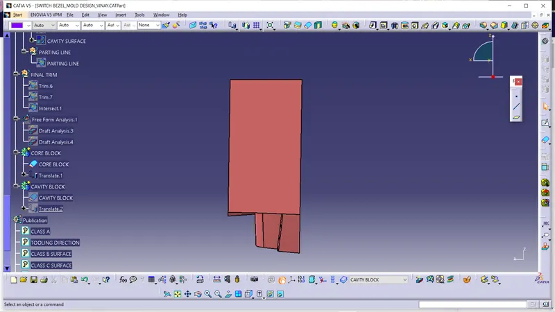
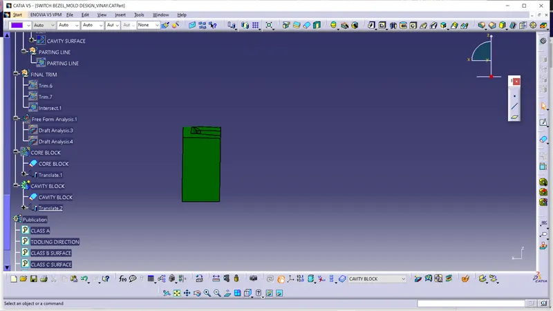
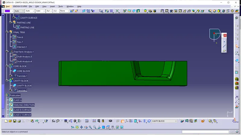
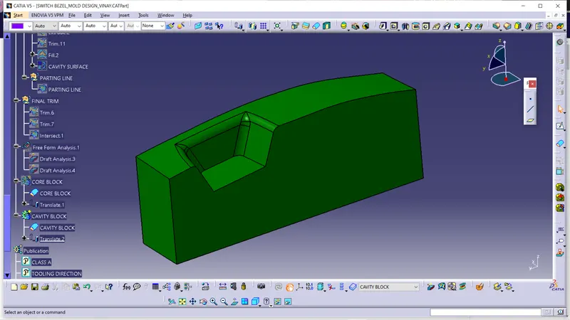
CAVITY BLOCK:-
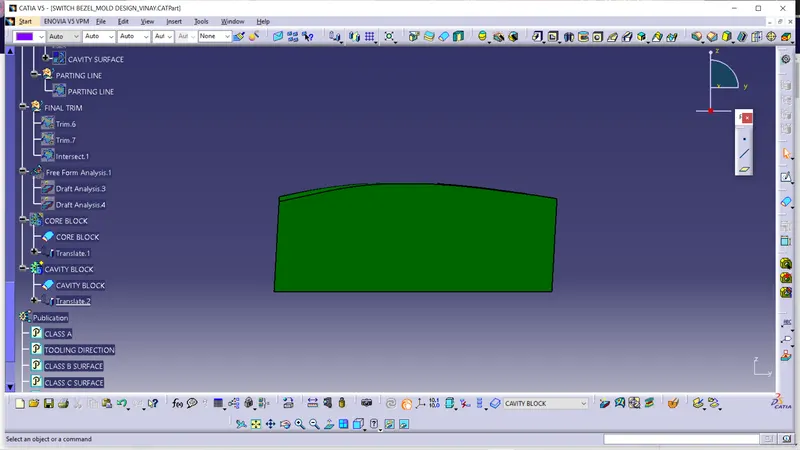
Cavity block is created by using the CLASS B SURFACE and extruded rectangle with tooling direction. we trimmed them both and created the closed surface for block. That is our cavity block.
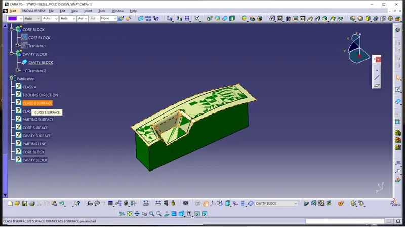
views of cavity block:-
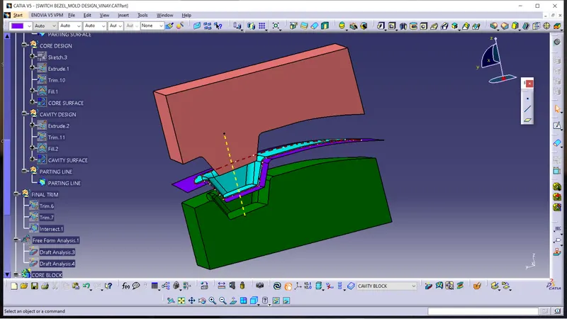
FINAL VIEW OF THE MOLD BLOCK:-
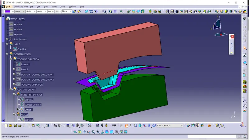
we created that with traslation of the CORE and CAVITY blocks for better view and understanding.
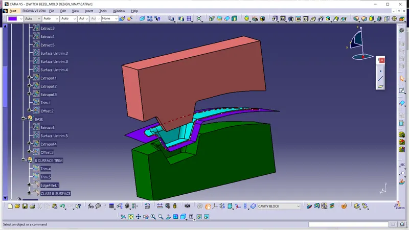
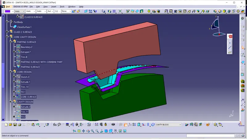
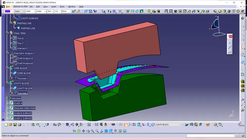
FEATURE TREE:-