Photo Realistic Rendering
MODELLING OF AMERICAN CHOPPPER IN SOLIDWORKS
:- SANKARI VINAY
INTRODUCTION
In this project we are learning designing of the American chopper bike on solid works and solid works visualize. We are designing different type of components in this American chopper. We will individually design them in the solid works and assemble them after that.
The components in the American chopper bike we learn about designing of :-
- Engine with exhaust system
- Front wheel and rear wheel with rims sprockets and calipers
- Chassis
- Front fork along with handlebars and grips
- Front and rear fenders
- Oil tank
- Gas tank
- Chain and transmission belt
- Kick stand and foot pedals
After designing of these parts we will learn about assembling of the all these components. Then we will learn about the rendering of chopper. We will learn about realistic view of the chopper by these rendering. We will learn about different views of rendering and visualize of a chopper in different scenarios.
DESIGN APPROACH:-
We start with the designing of the transmission belt to the end we are doing rendering of the final design of the chopper. The way we start the design and end by the rending of model is called as design approach. It will give us a clear view of modelling of any object in proper and clear way to understand the design procedure.
- Designing of transmission belt
- Designing of kickstand
- Designing of front& rear fender
- Designing of chain
- Designing of front wheel then rear wheel
- Designing of front fork
- Designing of chassis
- Designing of engine and exhaust system
- Designing of gas tank
- Assembling of the parts & give them appearance/colour
- Adding decals and editing appearance (if needed)
- Rendering of the model with different scenes and views
- Visualizing the chopper model
In designing of this model we will use some features in solidworks for required shapes& assembly. Let’s discuss about that features that we will mostly used in designing of the models in solidworks.
- Extrude boss:-
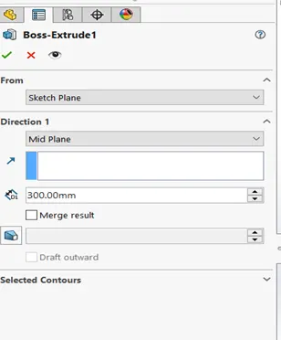
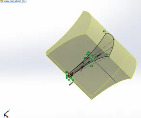
Extrude boss/ base feature is the basic feature in the solidworks model designing. This will used after creating a sketch with closed boundries. In this feature we we extrude/convert 2D model to 3D model with some width, height with some solid body.
This feature only used in straight path only. That means we extend in straight line only. We can also expand in two directions or some distance from the sketch also.
- Extrude cut:-
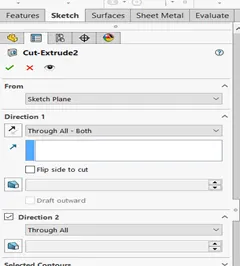
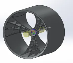
Extrude cut is also similar to the extrude boss but in opposite way. In extrude boss we add or create material but in extruded cut we will remove the material from the model that was already created. It’s also created with closed boundary sketches only. In this feature also we can remove parts in both directions of some distance from the sketch by using offset feature the dialog box or pop-up box in left side on screen(in from option).
- Fillet:-
Fillet is the feature used to provide the safe and clean edges to the solid body. It will give the nice finishing and good shape to the model. In fillet we convert sharp edges into round corners. In this we need to select the edges and apply diameter to the edges to be filleted.
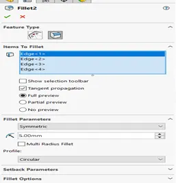
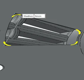
- Chamfer:-
Chamfer is also quiet similar to the fillet option but it won’t convert sharp edges into round corners. But it will convert them into angular edges by using distances and angles according to the requirements. We can covert sharp edges into incline or angular shapes according to the model.
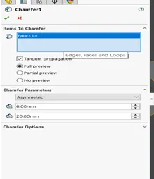
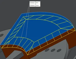
- Revolved boss/revolved cut feature:-
Revolved boss and revolved cut is similar to the extrude boss and extrude cut but the difference is extruding will be done in circular or revolved pattern instead of straight path/line. In revolved boss/cut the sketch will be drawn and it will cut or extrude by using a axis of revolution.
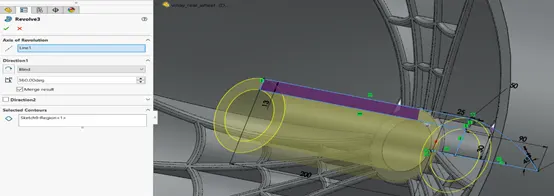
REVOLVED BOSS
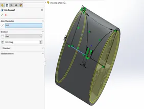
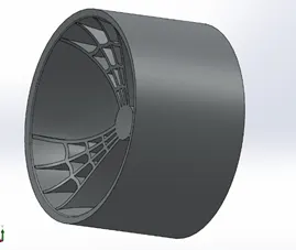
REVOLVED CUT
- Shell:-
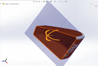
Shell is used to create hollow body or one side opened hollow body. Its mainly used to remove the inside body of the solid model and give the thickness to the outer body or at outer surface. It will give good solid modification to the modelling of any kind of hollow body.
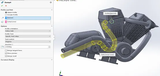
- Sweep boss/ Sweep cut:-
Sweep boss or sweep cut is used create or cut the part in a non-linear or curved path
with a given shape in that path. It is very useful in exhaust system or curved parts in the American chopper. Both features are similar but swept boss is used to create the solid body and swept cut is used to cut the solid body in the same method shown down.
- Loft boss/ Loft cut:-
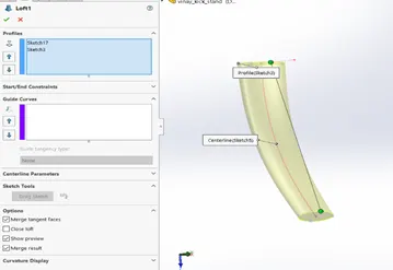
Loft boss or loft cut is used to create or cut the solid body with two non-linear shapes with using of guide curve. It is used for the create complex shapes in modelling. Its similar to sweep boss. In sweep boss we create using one shape and path but in loft boss/cut we create using two fixed shapes through the path.
- Linear pattern/circular pattern:-
Linear pattern is used to make more than one instances at a time like mirroring same object in a linear path one or two directions. This is used to reduce time and make exact same instance in repeated in equal distances. In same way circular pattern we will make instances in circular pattern. While using linear/circular pattern select the direction and give number of instances.
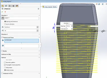
Linear pattern
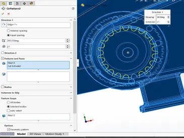
Circular pattern
- Mirror:-
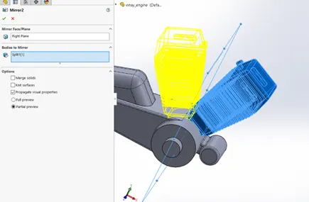
Mirror tool is used to mirror the object that was already drawn in one side of the axis and should be drawn with same dimensions on another side of the axis. It is used to project or draw same dimension object in modelling or sketching.
- Reference geometry:-
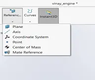
It is used to make a reference to the design or drawing that made in the solid works. It is used make the reference plane or axis. They are used to make the new sketch in the different angles or different points in the modelling or sketching.
- Projected curve/ composite curve:-
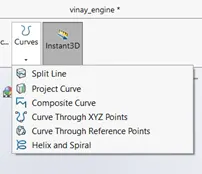
Projected curves used make model face to create a 3D curve. we can also generate intersection of two splines. That is also called as composite curve. We can also create multiple closed or open contour projected curves in a single sketch. In composite curves we will add two different splines/curves and make them composite to make required curve.
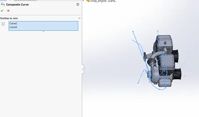
Composite curve
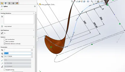
Projected curve
- Mate:-
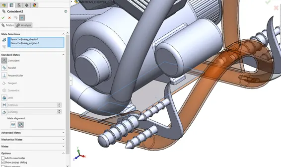
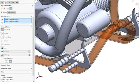
Mate is the relation that is used in the assembly to attach the parts of model. They are different type mates that used make the components assemble according to the usage or requirement. In assembly we will insert the parts and assemble them by using this mate. There are different type of mates used in the assembly coincide, concentric, parallel, tangent and some different type of mechanical mates.
- Combine:-
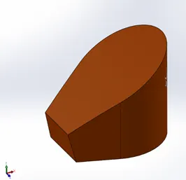
In combine we will combine different type of the parts and make them attached or make them in proper alignment. They are used make exact alignment or shape in modelling. In we can add, substract or common the parts.
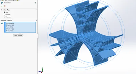
adding the parts
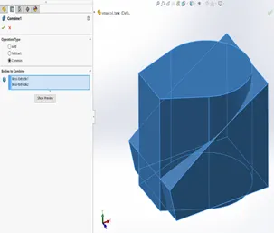
Before After
Common the parts
We are discussed about major tools and feature that we will use them in the modelling of the parts and assembly in American chopper. Now we start the modelling the each and every part individually with given dimensions in the solidworks then we assemble them. Now we will discuss about the each and every part individually.
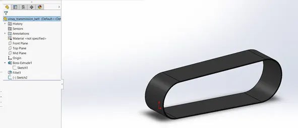
Transmission belt:-
Transmission belt is single extruded part surface that having the fillets on the edges of the surfaces. It having the appearance of the matte rubber. It is used to transmit the power from one pulley to another pulley.
Kick stand:-
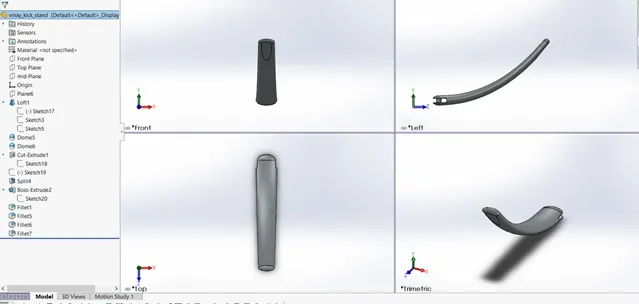
Kick stand is the lofted boss with having dome on the both edges. It is having some cut extrude and split feature applied on part. It is also applied fillets on the edges of the kick stand with some extruded part inside. Stand is used for giving the support to the bike when it is in stationary position or without any movement. It is having appearance carbon steel.
Front fender:-
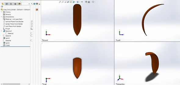
Front fender is a revolved boss with some angle and also applied of two kind split features at edges of the front fender with given dimensioned sketches. It is also fillet applied part at the corners and the edges of the fender for giving good and safe structure. This fender is used at the top of the wheel is protects from sand, dust and mud. Front fender is having siena appearance.
Rear fender:-
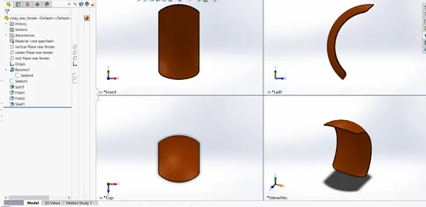
Rear fender also similar to the design of the front fender. It is a revolved boss with some angle revolve. It having some split feature applied and also having some fillets at the edges and corners of the fender for giving good and safe output of the model. It is also used for giving the protection from dust, sand and mud.
Oil tank:-
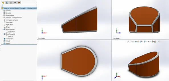
Oil tank is a part used to store the oil in it. It is a combination of two extruded bosses with having some shell feature applied with in it. And having some fillets at the edges and corners of the tank. It is located on the back side of the engine. Oil tank is siena on boss base and white coating the fillets that applied for better appearance.
Chain:-
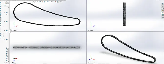
Chain is a part that is used transmit the motion from engines to wheels by using of the sprockets. It is a design that contains of block and path. In this design we design blocks for link for extrude. We create the extrude of the chain links and the uses the circular/linear patterns for copy and paste them. After that we will use mirror tool for project the same links on the other side of the parts in chain. We create upper and lower link blocks for the chain and extruded boss then we will use linear pattern then mirror then with using of axis. Chain is having chromium plate appearance on it.
Pedal:-
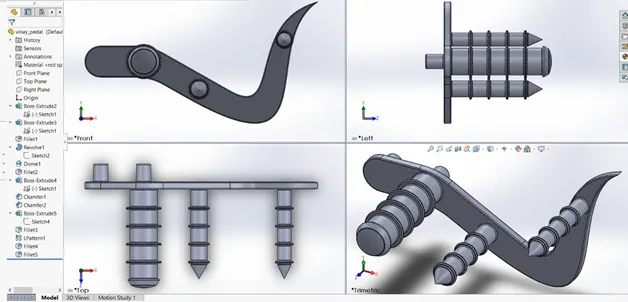
Pedal is extruded boss of two splines. Pedal is having another extrudes with having of the dome feature at the end. We will also use linear patten for making the exact model. Then we will apply some chamfers and fillets at required corners and edges for giving better output. It is used for placing foot on it. We need two pedals but we create only one and mirror that in assembling of chopper. Pedal is having carbon steel appearance.
Front wheel:-
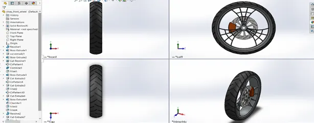
Front wheel is combination of caliper, rim, rotor and tire. Tire is revolved boss with linear pattern of extruded cuts on it with applied appearance of the matte rubber. Caliper is extruded boss with having chamfers on both sides of it. And caliper is having siena appearance on it. Then we have the rim with chromium appearance on it. It is a revolved boss with revolved cut body. And having extrude boss and extrude cut in the spokes of the rim and applied circular pattern to it then combine them. Rotor is a part which having the extruded boss with some extruded cuts on it with the applied circular pattern to it. It is having carbon steel appearance applied to it.
Rear wheel:-
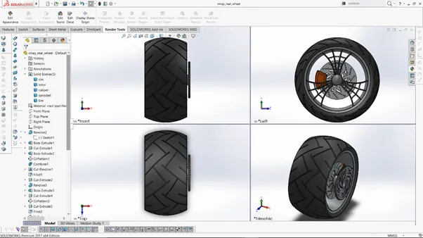
Rear wheel also similar procedure like front wheel with similar parts and one extra solid body is sprocket in it. This sprocket is used to transmit the motion from the engine to the rear wheel. The sprocket is extruded boss with circular pattern of extruded cuts on it. The appearance of sprocket is chromium plate and appearance of remaining parts is similar to front wheel.
Front fork:-
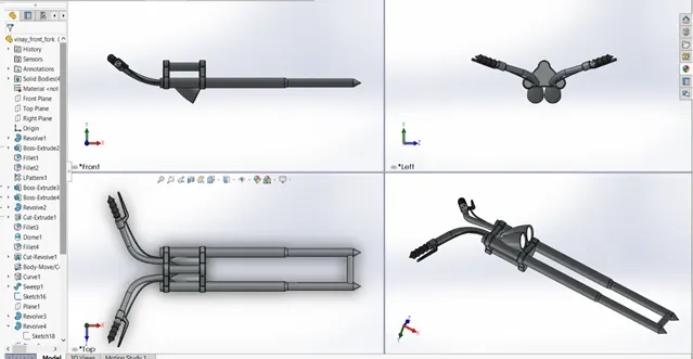
Front fork is the part it contains handle, head lights, wheel holding component and some wires. The fork will be designed one side and it will be mirrored another side. It will be having the extruded boss, revolved boss, extrude cut, revolve cut, combine parts, applying some fillets and chamfer to it. Create the planes for reference and moving objects the mirroring them after the design is completed on one side. Apply glossy rubber for handle, matte rubber for wire components that made by revolved boss. Apply chromium plate appearance for remaining parts.
Chassis:-
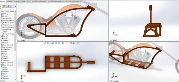
Chassis is the main frame of the chopper which is used to hold the engine on it and also holds the rear wheel and front fork with in it. It will give support to the gas tank also. The total body of chassis sweep boss and extrude bosses mainly. We will make some extrude cuts and fillets to it. It will be having the appearance of the siena. Frames are majorly made by the curves to design the chassis. It will be hollow in the shape to give less weight and more convenient.
Engine and exhaust system:-
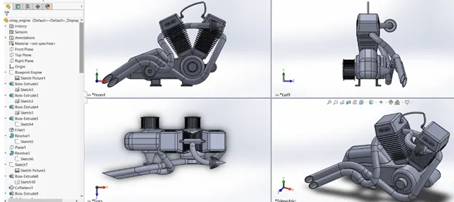
Engine is major part in chopper that will convert fuel in power which gives the motion to the chopper. It will contains the exhaust system with it which is used to remove the unwanted gasses from the engine after convert fuel energy into the power. In designing the engine we will use extrude boss, revolve boss, linear pattern, extrude cut, circular pattern and some fillets will be majorly used. And in exhaust system we will use curves, sweep boss, circular pattern, split tool and other required tools. For engine give some colored appearance like grey color or carbon steel.
Gas tank:-
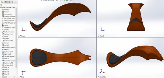
Gas tank the surface modelling part. It is used store the gas in it. This is majorly created by the curves, surface sweep, surface loft, boundary surface, surface extrude. And we would also knit surface for combining the surface of the tanks. We will also create seat with the surface features with given dimensions. The gas tank in type shell but it is a surface part so we are using the surface feature for designing of gas tank. We will also use the fillets for better and safe finish to the model. The gas tank is placed on the chassis. For gas tank we will use the grey cotton and for tank we will use the siena for the appearance. It will most curved and styled part in the chopper. We will use the composite curve for better look for the gas tank.
Assembly:-
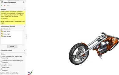
Assembly is the final part in making the model. It is used to join the parts of that made in the solid works till now. We will attach them one by one by using the inset components in assembling. Then we will use the mate option according the required mates and attachments needed. We insert the parts and adjust them according to the mate and then selects the parts or part areas of two different model then we select the type of mate. It is used for showing exact view of the parts after join them in reality.
Assembling is the most important and difficult part in the design. They should be done very carefully and proper way according to the requirements. Some times one mate will interrupt another mate. So, while doing we should proper mates and sometimes, we can use suppress and unsuppress the mates according to the usage or requirement.
INSERT COMPONENTS
MATE
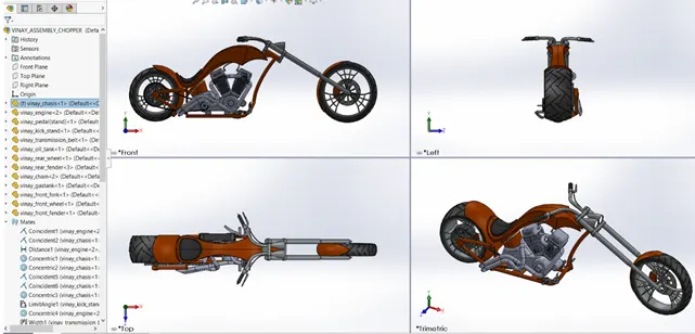
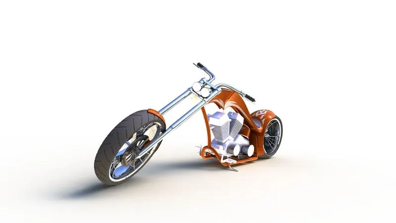
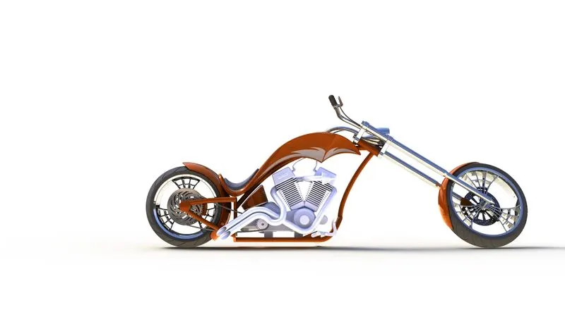
FULL ASSEMBLY OF AMERICAN CHOPPER
RENDERING :-
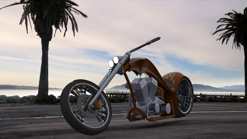
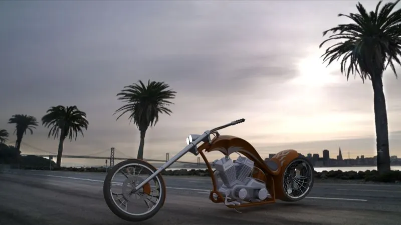
Rendering is the feature that is used to show the realistic image of the American chopper. It will show us the view of the American chopper in regular life style and environment. Rendering will give the image of the chopper in different locations of reality.