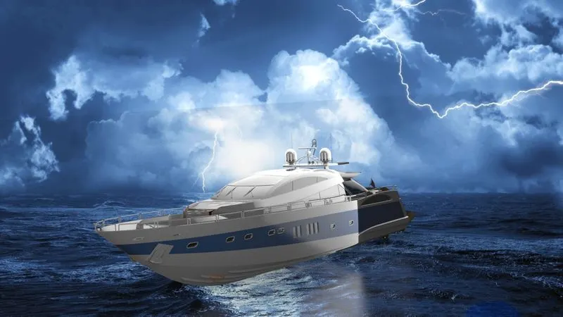
Radar Mast & Final Assembly of Yacht
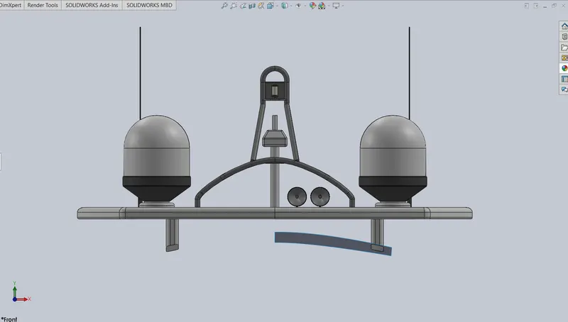
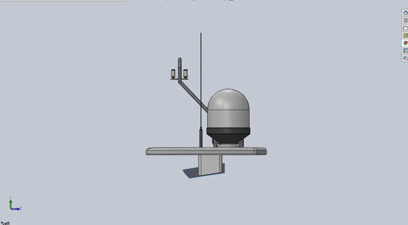
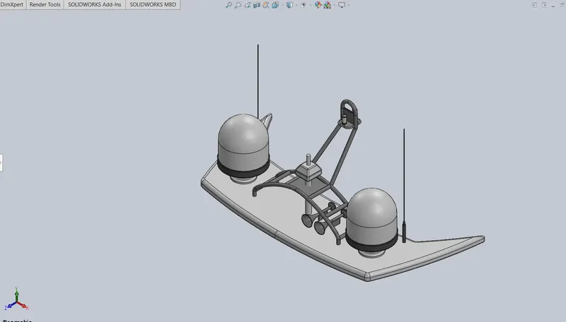
RADAR MAST:-
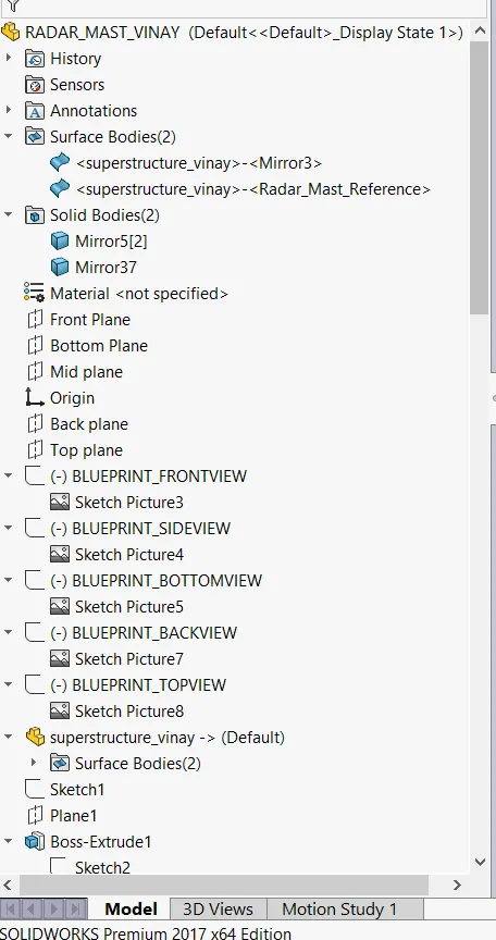
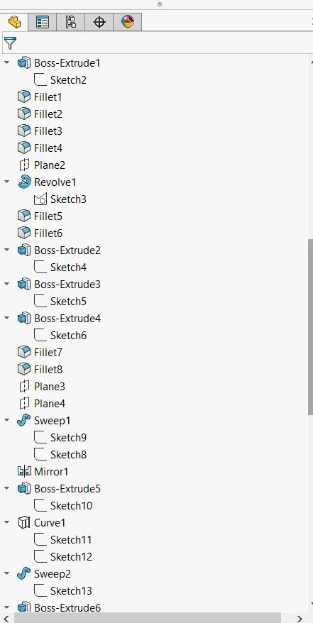
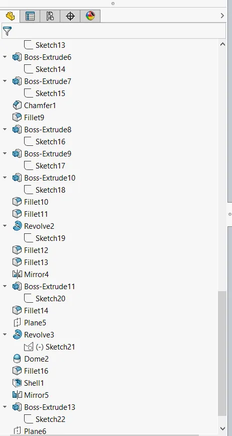
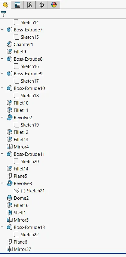
MODELLING OF SUNSEEKER PREDATOR YACHT IN SOLIDWORKS
:- SANKARI VINAY
INTRODUCTION
In this project we are learning designing and rendering of the sunseeker predator yacht on solid works and solid works visualize. We are designing different type of components in this yacht. We will individually design them in the solid works and assemble them after that.
The components in the Sunseeker predator Yacht we learn about designing of :-
- Propeller
- Radar
- Blue print (for reference purpose)
- Hull
- Garage door
- Front seat
- Middle seat
- Rear seat
- Super structure
- Radar mast
After designing of these parts we will learn about assembling of the all these components. Then we will learn about the rendering of yacht. We will learn about realistic view of the chopper by these rendering. We will learn about different views of rendering and visualize of a chopper in different scenarios.
DESIGN APPROACH:-
We start with the designing of the propeller the yacht to the end we are doing rendering of the final design of the yacht. The way we start the design and end by the rending of model is called as design approach. It will give us a clear view of modelling of any object in proper and clear way to understand the design procedure. It will gives a view of start design of the model in proper way and step by step to make the design of product as much as easy that can be happens.
- Designing of propeller
- Designing of radar
- Creating the blue print of yacht
- Designing of hull
- Designing of garage door
- Designing of front seat, middle seat& rear seat
- Designing of super structure
- Assembling of the parts & give them appearance/colour
- Adding decals and editing appearance (if needed)
- Rendering of the model with different scenes and views
- Visualizing the chopper model
In designing of this model we will use some features in solidworks for required shapes& assembly. Let’s discuss about that features that we will mostly used in designing of the models in solidworks. With using of those features we can make the required model with some good and smooth finishes
- Extrude boss:-
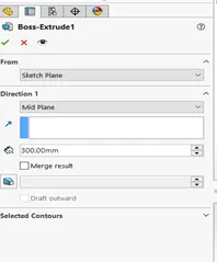
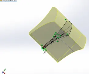
Extrude boss/ base feature is the basic feature in the solidworks model designing. This will used after creating a sketch with closed boundries. In this feature we we extrude/convert 2D model to 3D model with some width, height with some solid body.
This feature only used in straight path only. That means we extend in straight line only. We can also expand in two directions or some distance from the sketch also.
- Extrude cut:-
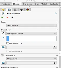
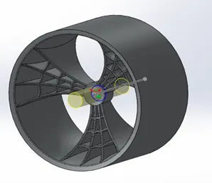
Extrude cut is also similar to the extrude boss but in opposite way. In extrude boss we add or create material but in extruded cut we will remove the material from the model that was already created. It’s also created with closed boundary sketches only. In this feature also we can remove parts in both directions of some distance from the sketch by using offset feature the dialog box or pop-up box in left side on screen(in from option).
- Fillet:-
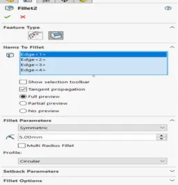
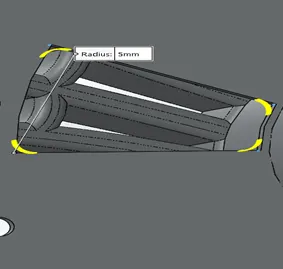
Fillet is the feature used to provide the safe and clean edges to the solid body. It will give the nice finishing and good shape to the model. In fillet we convert sharp edges into round corners. In this we need to select the edges and apply diameter to the edges to be filleted.
- Chamfer:-
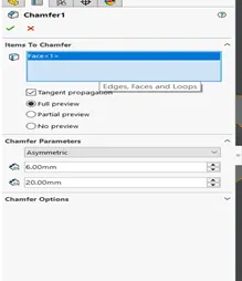
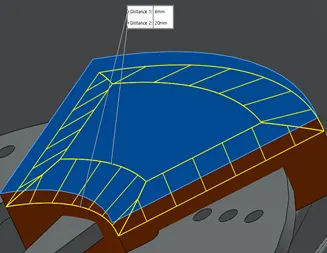
Chamfer is also quiet similar to the fillet option but it won’t convert sharp edges into round corners. But it will convert them into angular edges by using distances and angles according to the requirements. We can covert sharp edges into incline or angular shapes according to the model.
- Revolved boss/revolved cut feature:-
Revolved boss and revolved cut is similar to the extrude boss and extrude cut but the difference is extruding will be done in circular or revolved pattern instead of straight path/line. In revolved boss/cut the sketch will be drawn and it will cut or extrude by using a axis of revolution.
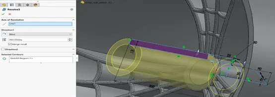
REVOLVED BOSS
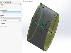
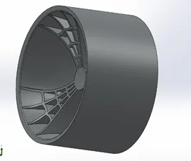
REVOLVED CUT
- Shell:-
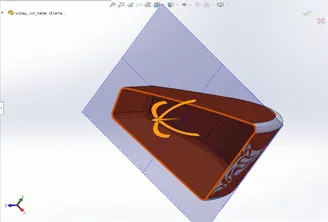
Shell is used to create hollow body or one side opened hollow body. Its mainly used to remove the inside body of the solid model and give the thickness to the outer body or at outer surface. It will give good solid modification to the modelling of any kind of hollow body.
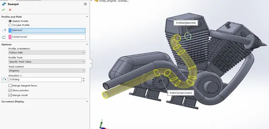
- Sweep boss/ Sweep cut:-
Sweep boss or sweep cut is used create or cut the part in a non-linear or curved path
with a given shape in that path. It is very useful in exhaust system or curved parts in the American chopper. Both features are similar but swept boss is used to create the solid body and swept cut is used to cut the solid body in the same method shown down.
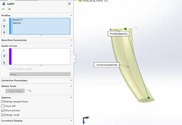
- Loft boss/ Loft cut:-
Loft boss or loft cut is used to create or cut the solid body with two non-linear shapes with using of guide curve. It is used for the create complex shapes in modelling. Its similar to sweep boss. In sweep boss we create using one shape and path but in loft boss/cut we create using two fixed shapes through the path.
- Linear pattern/circular pattern:-
Linear pattern is used to make more than one instances at a time like mirroring same object in a linear path one or two directions. This is used to reduce time and make exact same instance in repeated in equal distances. In same way circular pattern we will make instances in circular pattern. While using linear/circular pattern select the direction and give number of instances.
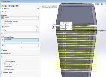
Linear pattern
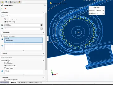
Circular pattern
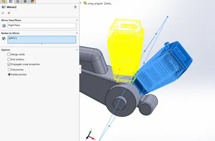
- Mirror:-
Mirror tool is used to mirror the object that was already drawn in one side of the axis and should be drawn with same dimensions on another side of the axis. It is used to project or draw same dimension object in modelling or sketching.
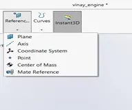
- Reference geometry:-
It is used to make a reference to the design or drawing that made in the solid works. It is used make the reference plane or axis. They are used to make the new sketch in the different angles or different points in the modelling or sketching.
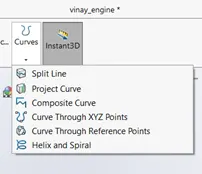
- Projected curve/ composite curve:-
Projected curves used make model face to create a 3D curve. Projected curve is used to project the curve at required area where we can’t create the splines and curves with specific location/area. We can also generate intersection of two splines. That is also called as composite curve. We can also create multiple closed or open contour projected curves in a single sketch. In composite curves we will add two different splines/curves and make them composite to make required curve.
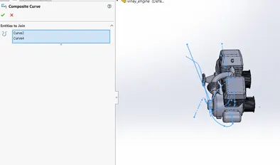
Composite curve
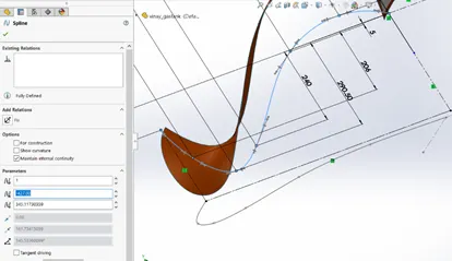
Projected curve
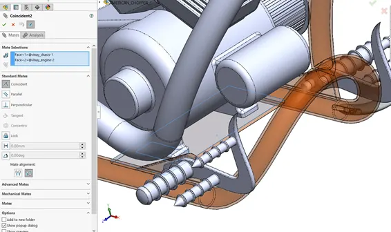
- Mate:-
Mate is the relation that is used in the assembly to attach the parts of model. They are different type mates that used make the components assemble according to the usage or requirement. In assembly we will insert the parts and assemble them by using this mate. There are different type of mates used in the assembly coincide, concentric, parallel, tangent and some different type of mechanical mates.
- Combine:-
In combine we will combine different type of the parts and make them attached or make them in proper alignment. They are used make exact alignment or shape in modelling. In we can add, substract or common the parts.
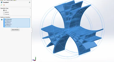
adding the parts
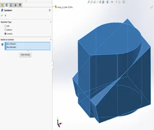
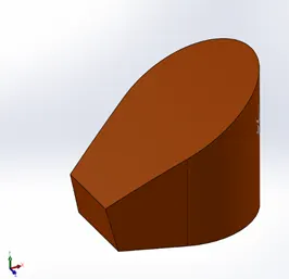
Before After
Common the parts
We are discussed about major tools and feature that we will use them in the modelling of the parts and assembly in American chopper. Now we start the modelling the each and every part individually with given dimensions in the solidworks then we assemble them. Now we will discuss about the each and every part individually.
In the similar way we have some features in the surface modules in solid works.
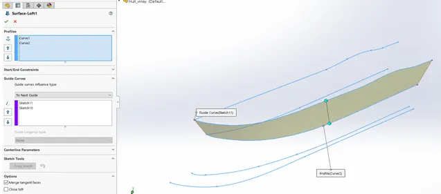
- Surface loft:-
Surface loft is the feature which is used to create the lofted surface by using the 4 individual lines or splines/curves. We will use the two of them as profile curves and remaining two curves as the guide curves which is used to guide loft surface.
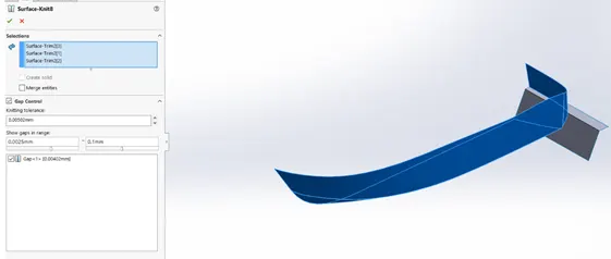
- Surface knit:-
Surface knit is the feature which is used to knit surfaces and combine different surfaces in the model. We can also covert the closed surface into the solid bodies after knitting them together. This is very easy and convenient feature to create a solid body with surfaces.
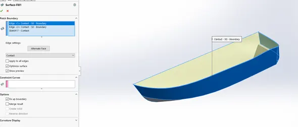
- Surface fill:-
Surface fill is used to fill the flat and open area in between the two extruded surfaces. We generally used it from fill the surfaces where we don’t need to draw extra curves or lines for the model for creating the new surface. It is very handy tool to create the surface between the two surfaces.
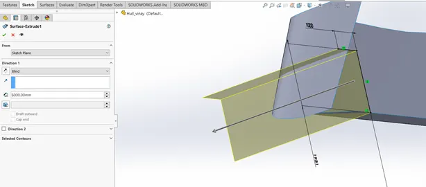
- Surface extrude:-
Surface extrude is similar to the boss extrude feature but this operation performed by the only single lines not like closed boundaries in extrude boss. Extrude surface will be same as extrude surface but it’s just thin surface according required distance.
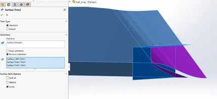
- Surface trim:-
Trim feature used for removing the unwanted material in the surfaces of the model the we created. We will use the on trim tool (sketch/part) to remove the surfaces according the requirement. We can use the remove selection or keep selection according to the convenience.
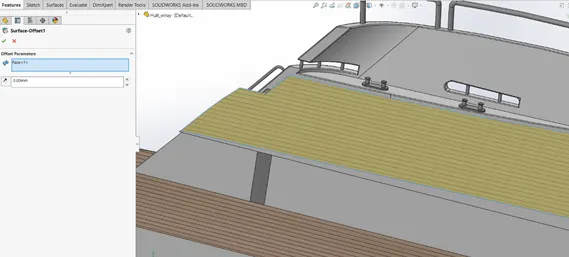
- Surface offset:-
Surface offset is used for offset the surface which was already created. This feature is used to reduce the time in creating the two similar surfaces twice or more in same axis or direction.
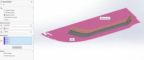
- Ruled surface:-
Ruled surface is used to extend the surface with some reference and we can also give some angle to the extended surface. We give the tangency and tapered angle and perpendicular relation to the reference surface according to the requirements.
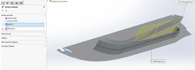
- Surface sweep:-
Surface sweep also similar to the sweep boss but here we will use both single lines or splines for the sweep. We generally select the profile sketch and path sketch for the sweep option.
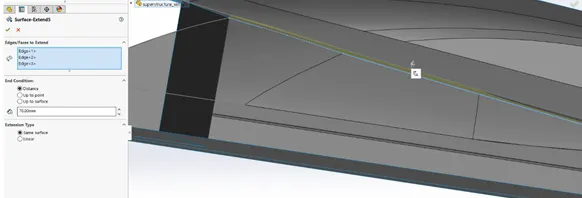
- Surface extend:-
Surface extend is the feature which is used to extend the surfaces already created for better output required shapes. Majorly used for close the surfaces with this feature. We can give the distance or select up to point surface.
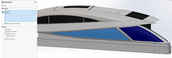
- Delete face:-
Delete face is used when the little mistake or wrong happens in the designing of the model. We can use it as deleting he face and fill the area of the face which we have deleted. It like give the patch to the removed area or open area after using of the delete face.
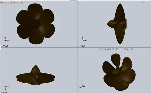
- Propeller:-
Propeller are placed at the end of the ship which contains the two or more than two blades. Propellers are used to propel the ships or move the ships by using the power that generated by the engine. Propellers create the thrust to move the ships. The design of the propellers depends on the conditions and requirements of the ship or any marine vehicle. It might be the ship, yacht, war ship or submarine. The kind materials will be varies for manufacturing of these propellers according to load and depth of sea where they were used.
2. Radar:-
Radar is placed on top of the radar mast which is used to detect the obstacles and ships in the marine/sea. Radar rotates in clockwise direction. Radar will produce the electromagnetic waves which will reflects in return if they hit any kind of objects in the range of waves. ( Note:- in marine/sea distance measured in the nautical miles and the speed will be measured in the knots)
1nautical mile=1.15mile=1.8km and
similarly the speed is also measured in the terms of
20knot=23mph=37km/hr
Radar are having different type of screens to detect different kind of obstacles according to the range, height, type of objects. The range of radar depends on the radar mast and type marine we used like transport or war ship it varies according to the usage.
`
3.Blue print:-
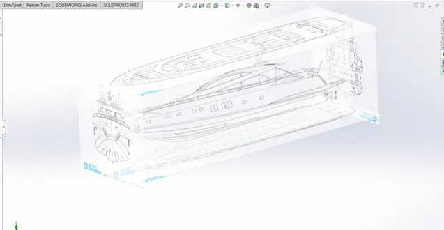
Blueprints are used as reference in design to get the desired and required output. They are used to give a sample view of the model and vision to create the model. The blueprint will be created by view picture of the front, side, back, top, bottom of the models and the combining of these pictures will give us a view for modelling of the object/part.
4. Hull :-
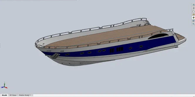
Hull is the major and important and visible part in the yacht that will be created. It will be the on which touches water and holds everything with in it and on it. Hull is water tight body of the ship or yacht. Hull is used to hold the super structure in the yacht. But it can be full or partially covered wit the deck. It contains the machinery, open area, cargo and accommodation in ship or yacht. It will be majorly used for protecting the ship from weather conditions, floods and any kind of structural damages that will occurs in the sea. It will be having major portion of the ship/yacht’s body.
The design of the hull depends on the usage or type of the ship/yacht. If it’s a warship it will be fully closed for security purpose, if it is a cargo ship it will fully opened and also having large open area to carry the cargo or goods, if it is a private yacht it will contain some open area, seats, super structure and required things according to their need.
5. Garage door:-
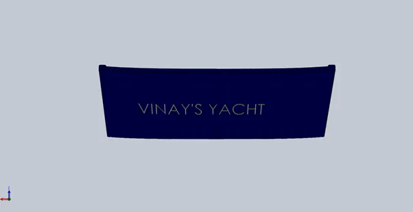
Garage door is used to close the garage where we keep the vehicles for transportation. It might be automated door or manual door that depends on the type ship/yacht. It’s just normal door type but it will be having the more strength to protect from the problems in the sea.
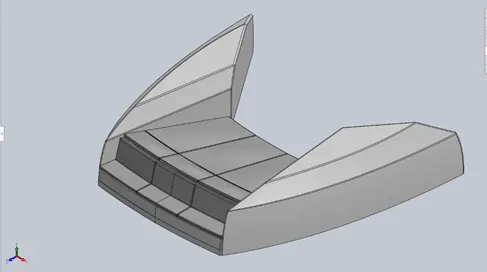
 6. Front seat:-
Front seat which is placed on the hull in the front of the ship. Which is used to enjoy the view point in sea. It will be placed in-front of the super structure.
7.Middle seat:-
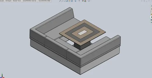
Middle seat is placed at the back of the hull. It is placed in between the super structure and the rear seat. It will contain the table also for having dinner or drinks. It will be open square model and seating capacity will 6 comfortably.
8.Rear seat:-
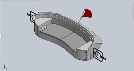
Which placed at the end of the ship. It will be just behind the middle seat. Which is having the seating capacity of the 3members. It will also contain doors at the sides of the seat and a flag on it for representing its company or type of ship.
9.Super structure:-
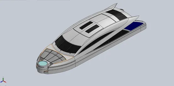
Super structure is placed on the hull of the ship. The part which is constructed above the ground level is called as super structure. Super structure includes beams, columns, doors, windows, roofs and kind of finishes of the ship/yacht. It will give the stylish and modern look to the yacht in design. The superstructure is containing the space for accommodation facility to passengers or owners.
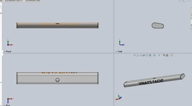
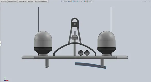
10.Radar mast:-
Radar mast is placed on the superstructure of the yacht. Which will holds the radar for detecting the obstacles and ships. Radar mast having the antennas on it for receiving the electro-magnetic waves that released by the radar. It will give the indication or signals to the display or monitors. It will receive the different type of the signals so for detecting different type of obstacles in the sea. It will also having the horns on it.
11.Final assembly of sunseeker predator yacht:-
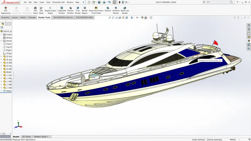
The final combination or final product of the yacht after adding the parts of the yacht that designed in the solid works. This will be the final view of the yacht. The assembly will also in the solid works by using of mate option in the solid works assembly. In assembly we can arrange or fix parts of the yacht in exact and fixed palce. We can also give rotational or any kind of motion that required.
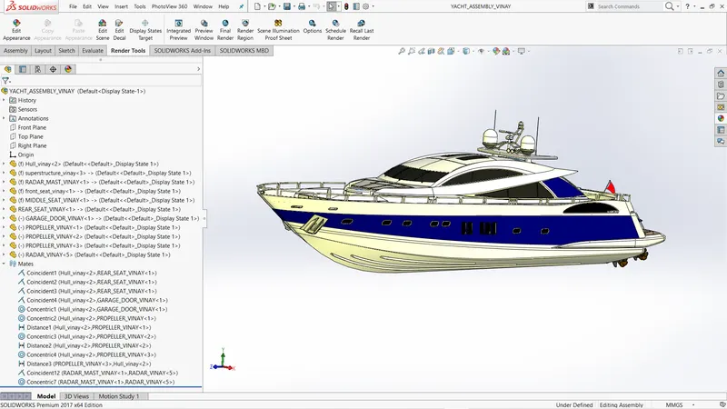
mate relations of the yacht assembly feature tree
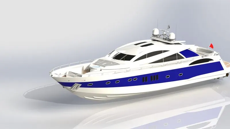
12. Render images:-
Final render images of the yacht after the final assembly
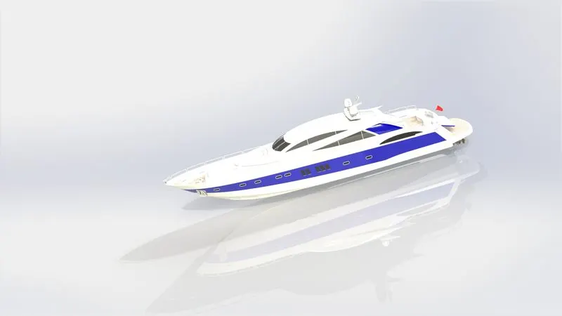
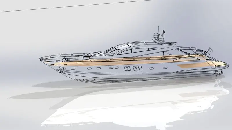
13. Visualize images:-
Visualized images of the yacht created in solid works visualize after assembling
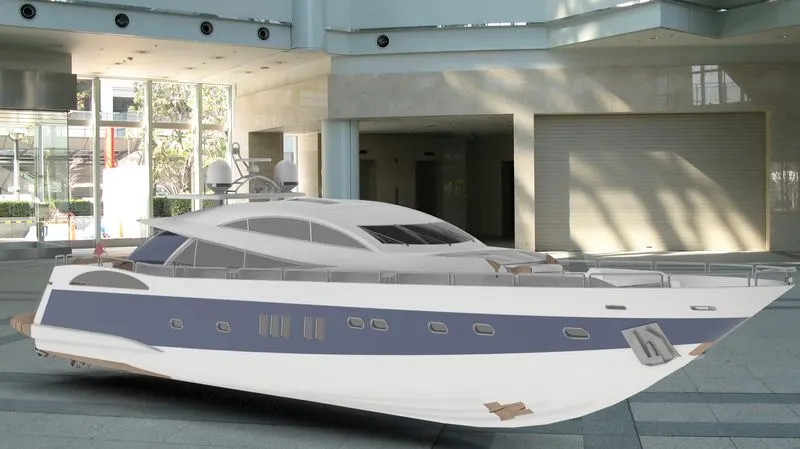
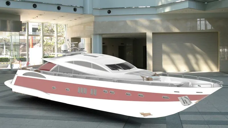
( NOTE:- The above two pictures are taken for showing the reference of the yacht after doing visualize in the solid works visualize. because they are not placed on land like this way without any attachments to it.)