Week 8 - Challenge 5 - Core & Cavity Design
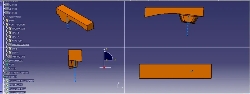
Report:
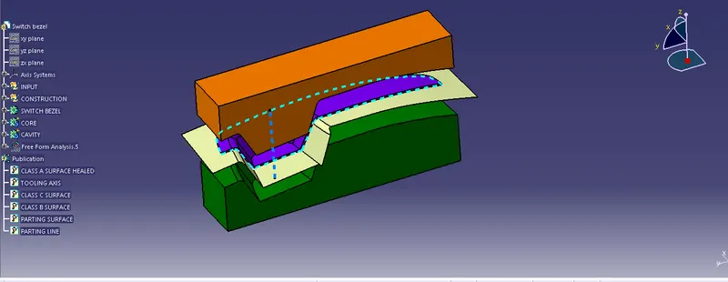
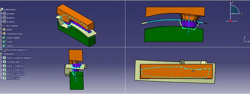
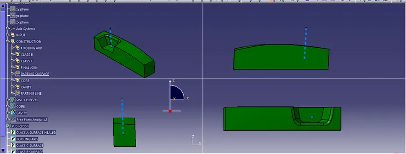
Input class A surface was checked for the suitable view with respect to which a toolig direction could be selected, avoiding the under cuts and side core requirement.
Firstly view along Z axis was checked and found that it is feasible to create tooling direction along Z axis.
Point created on the middle of base surface and an axis system created on the point. A sketch created in YZ plane along the new coordinate system and extracted the side walls . A bisecting line created for through these two lines.
Sketch created along XZ plane along the new coordinate system. line created passing through the point created earlier and at an angle of 3 degree vertical to base face.
A bisecting line for the two lines created earlier made. This line will be the tooling direction for the part.
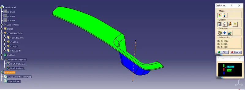
Once the model is created, do a draft analysis of the part. if the side walls draft angle is less than 3 degree, increase the line angle in the sketch created earlier.
Draft analysis shows that there is excess material provided on the junction of class b to class c surface(near parting line) such that in case if there is any mold defect (mainly flash or mismatch), the face can easily be machined / trimmed without compromising on the critical exterior face.