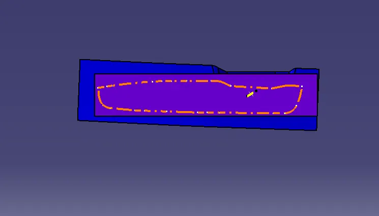
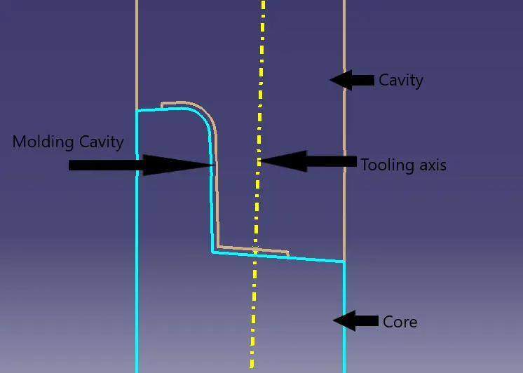
Week 8 - Challenge 5 - Core & Cavity Design
Objective:
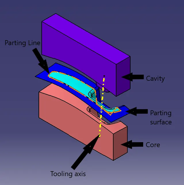
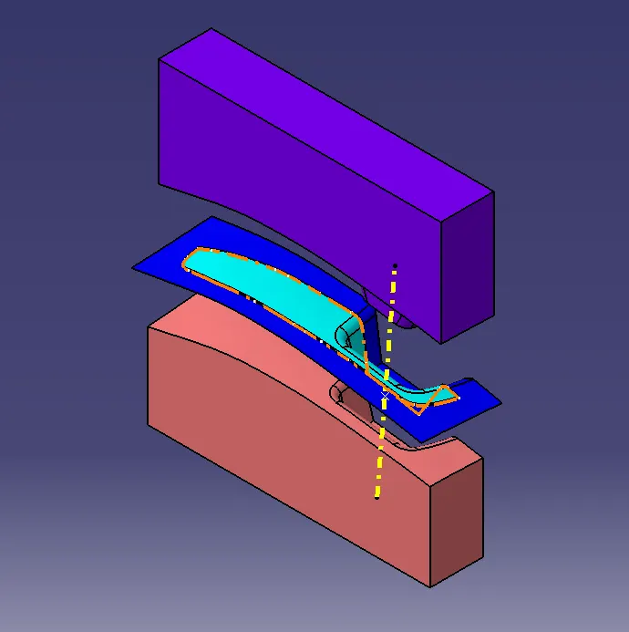
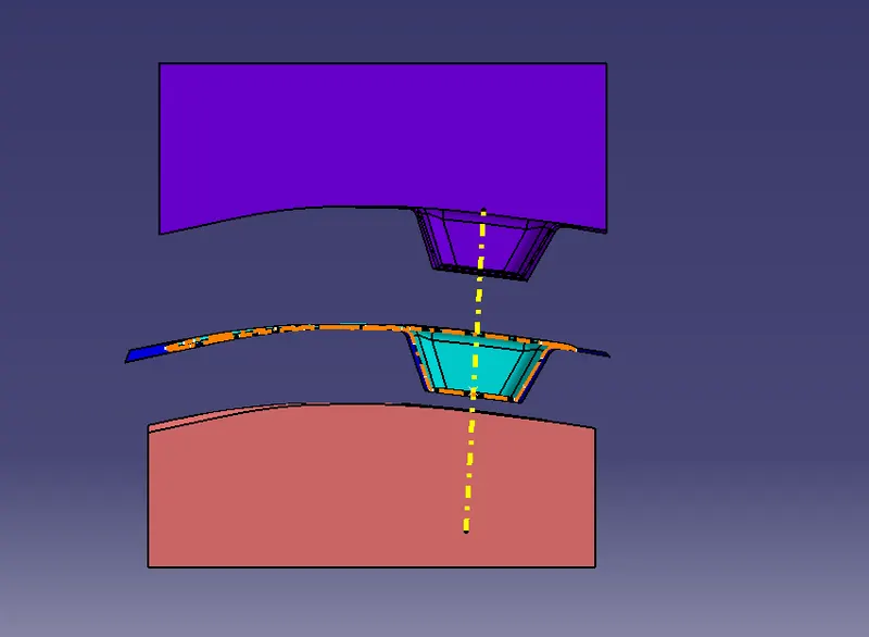
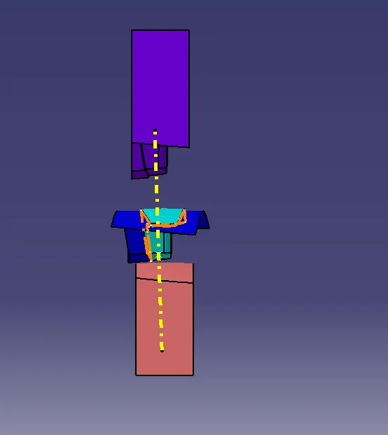
To create the Core and cavity blocks for the switch bezel designed in the earlier challenge.
Asnwer:
1) Draft Analysis
Draft analysis is done to ensure that the designed part is manufacturable based on the draft conditions applied. It is done to ensure the proper ejection of the component from dies(for metals) or molds(for plastics). The basic idea is to ensure that the tooling axis has to be created in such a wat that it has no parallel surface profiles of the component so that the ejection of the components can be ensured . Tooling axis is the axis along which cavity and core are closed and opened .
2)Procedure for creation of tooling axis using bisecting method .
Step 1: Import the model and check for surface continuity and connectivity using Join tool .Ensure there is no surface gap
Step 2: Insert a geometrical set . Ectract the base surface and create a point at its center using point on surface option from point tool. Look for suitable axis to create a tooling axis so that all faces clear tooling .
Step 3: Create an axis system without current option ticked at the above point. Create a position sketch with zy plane from axis system and above point as reference point.
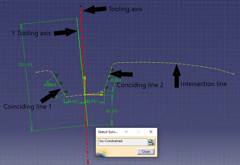
Step 4: Use intersect 3d objects option from project tool to create 2 lines by selecting a suitable plane(zy). Now create 2 lines which coincide with lines on both sides of the projection point . Create a line using bisect option .Allign the line in required axis direction.This is our Y tooling axis .
Step 5: To create tooling axis about x direction, create a position sketch with xz plane as reference plane and projection point as the first point we created . Use cut section tool and create an intersection using projection tool . Now create a line that coincides with this line .
Step 6 : Draw a line from origin in horizontal direction and create and angle constraint of 5 degrees. Use bisect option to create a line between that above lines . This is out X tooling axis .
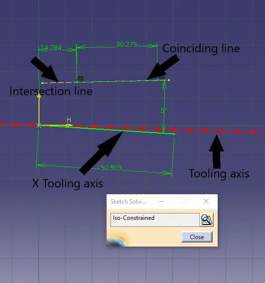
Step 7 : Create a new line using bisect option between X tooling and Y tooling line . this is our required Tooling Axis , Name this as tooling axis and publish it .
Procedure to check for Draft analysis
1)Once the tooling axis is created , publish it and the component using Publication from tool option .
2)Insert Feature draft analysis option from insert tool bar
3) Change the view option to customize view parameters and click om material option under shading .
4) Now click on the axis option from Draft analysis tools , allign it with tooling axis and click on lock option to lock it .
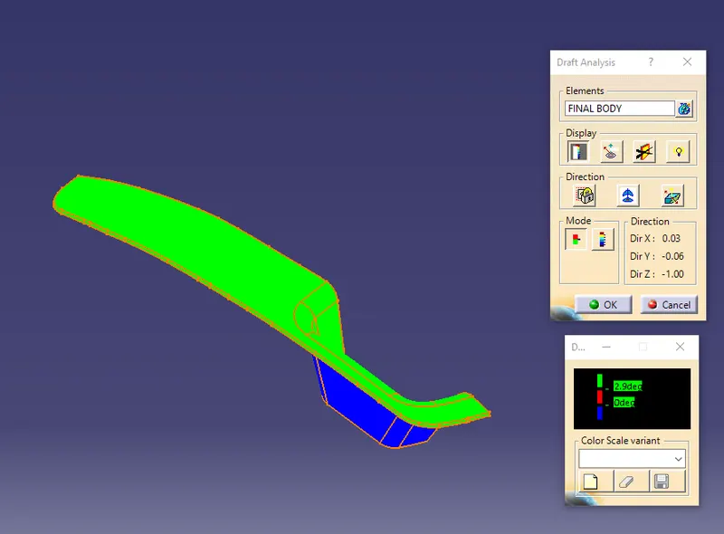
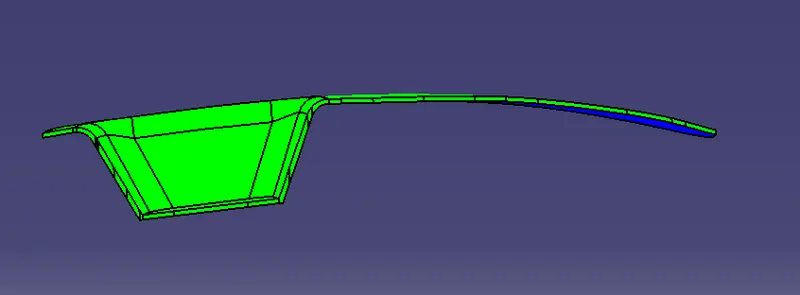
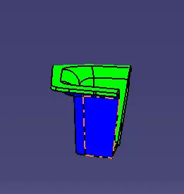
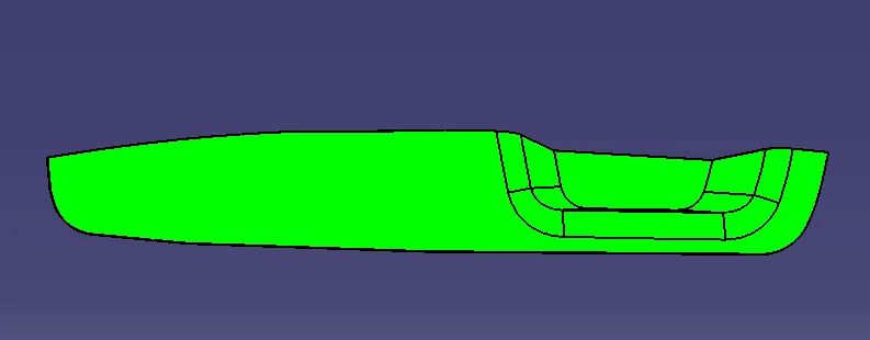
5) Change draft angle value to 3 degree . Click on quick analysis mode to display feature according to given color scale . Check from all views to ensure the draft analysis is cleared . Click ok to complete the Draft analysis mode.
Draft analysis on Class A
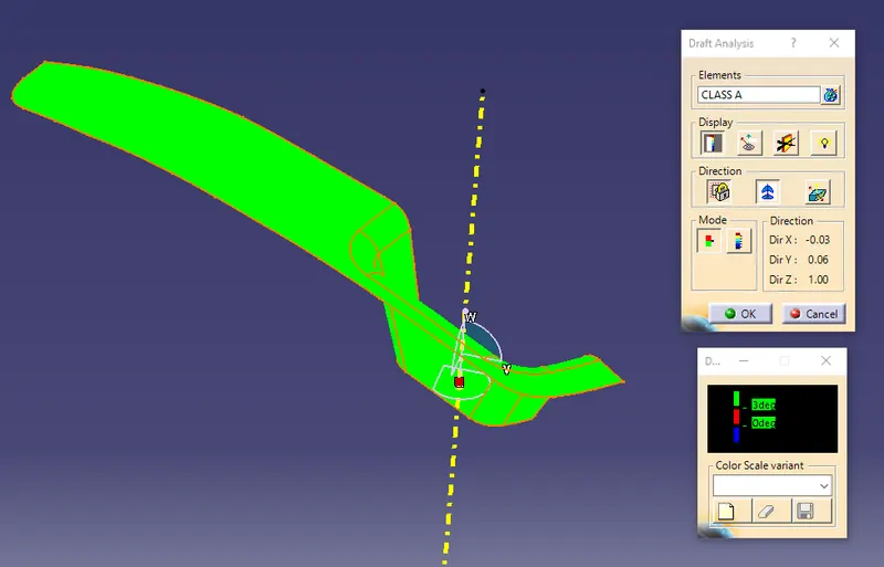
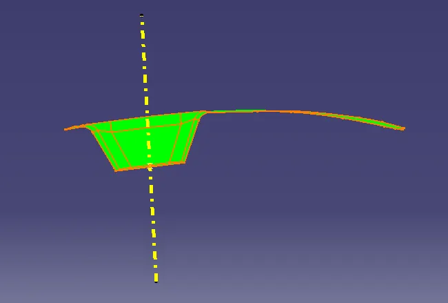
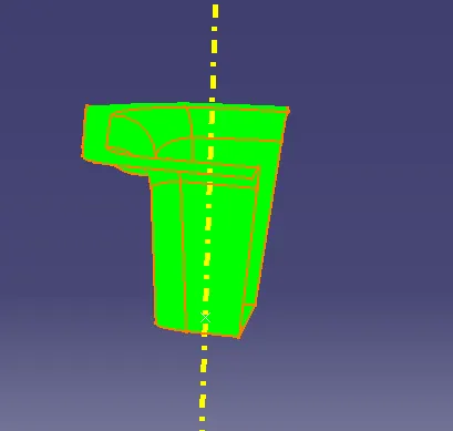
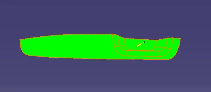
Draft Analysis on solid model
Core and Cavity Design