Week 8 - Challenge 5 - Core & Cavity Design
DESIGN OF CORE AND CAVITY
OBJECTIVE
- To perform draft analysis over the plastic component
- To design core and cavity
DRAFT ANALYSIS
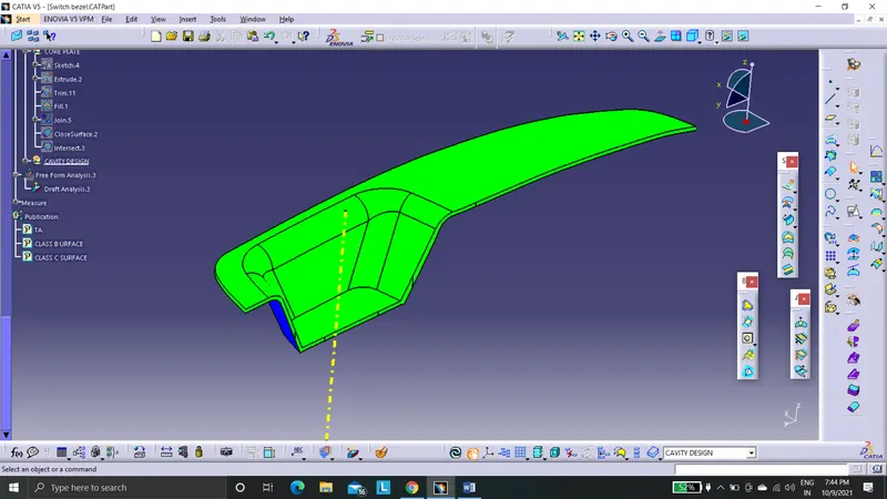
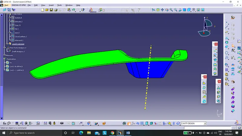
The switch bezel plastic component is chosen for core and cavity design. Before entering into it we need to decide the directions of core and cavity. By performing draft analysis we come to know the class A surface and class C surface can be fed as core plate where the class B surface is fed as cavity plate. The minimum draft which the component possess is 3 degrees.
CORE AND CAVITY DESIGN
1.Parting surface
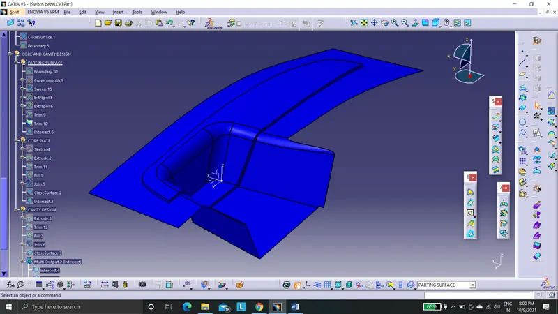
It is the surface where the core and cavity plates touch each other. Always the interference region is on class B surface. This is because to avoid the flash defects in class A surface. If the flash points were in the class A surface that leads to lower the aesthetic quality of the component.
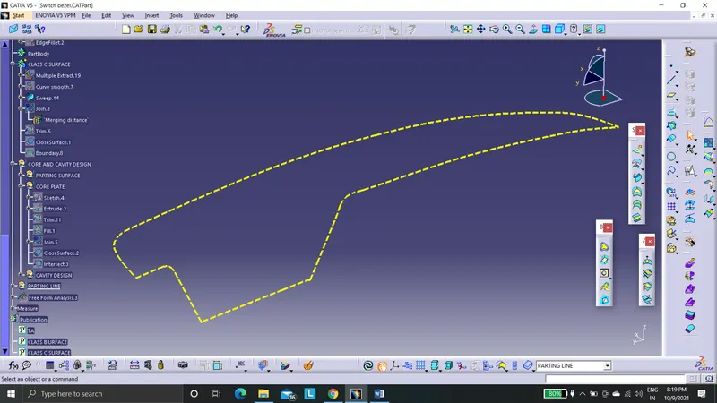
2.Parting line
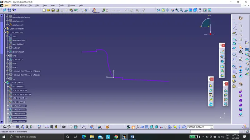
It is a line were the draft angle changes its direction. It is the junction of core, cavity and parting surface.
3.Core plate
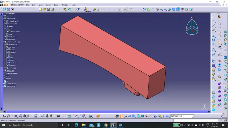
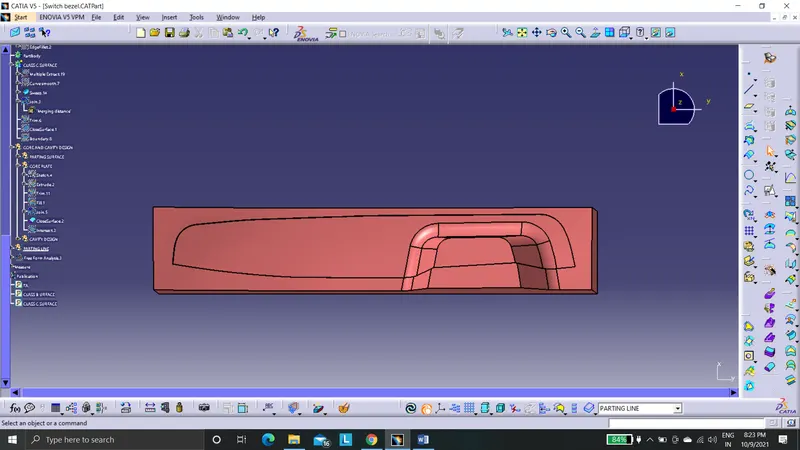
The core plate has the design of projections. It is developed using parting surface. We have to make sure that the core has to clear draft in its direction of opening and closing. Extrude the parting surface along the tooling axis direction.
4.Cavity plate
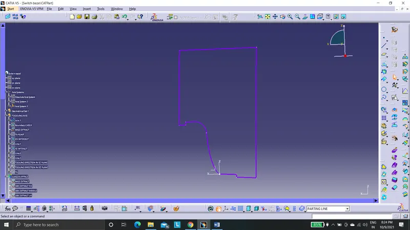
Cavity plate has the design of vacuum in it. It can be developed using the class B surface.
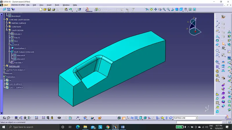
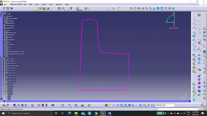
CORE AND CAVITY
The core and cavity are brought close to each while molding.
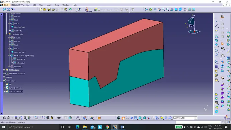
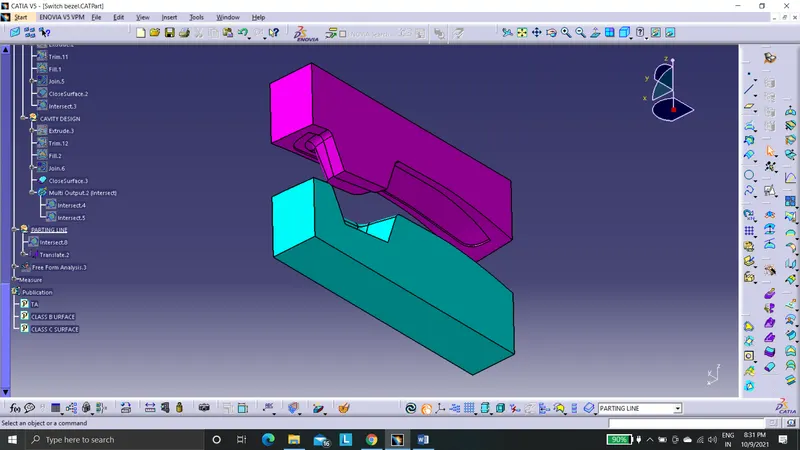
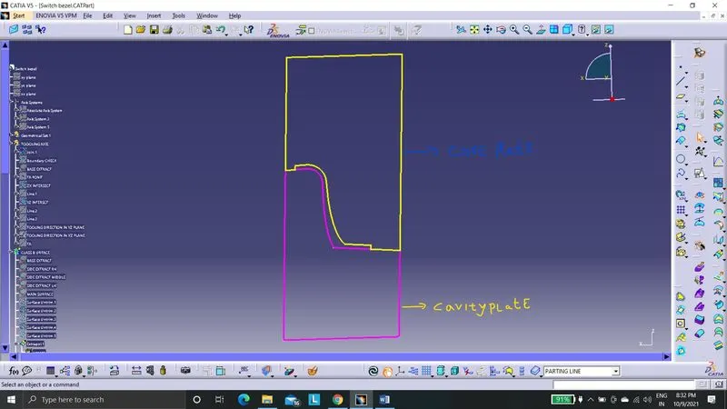
The yellow lines indicate the profile of ore plate. The pink lines indicate cavity plate profile. Class A surface and class C surface were molded using core plate while class B surface molded using cavity plate.
CONCLUSION
The core and cavity is designed for a plastic component.