Switch Bezel Core & Cavity Design
SWITCH BEZEL CORE AND CAVITY DESIGN
Creating Final Tooling Direction (Axis):
- For obtaining the final tooling direction, we will consider all the 3 axes and view the part along them.
- We extract the bottom surface and take a point at its center. Insert an axis system at this point with all the 3 axes along the original directions.
- After viewing the part in different views, we can conclude that direction along Z axis is appropriate for our tooling axis.
- For that we will consider tooling clearing along both X axis and Y axis.
- For X direction tooling clearing, as shown below, we take intersection of the given surface body along YZ plane of the new axis system.
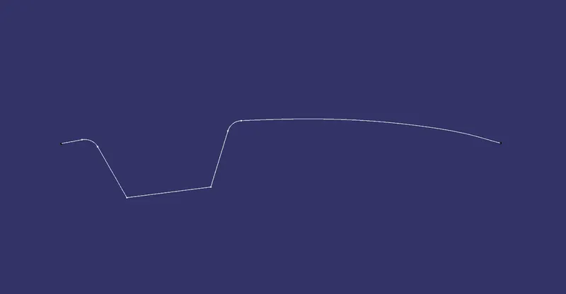
- Then we extend the lines in intersection that are inclined to Z axis as shown below.
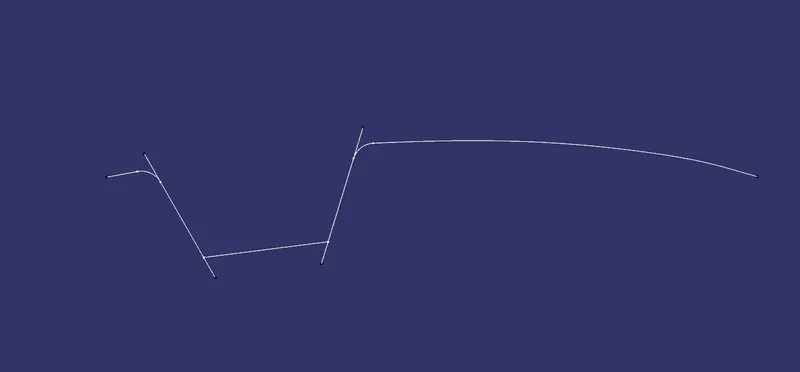
- Now create a line by bisecting these 2 lines as shown below.
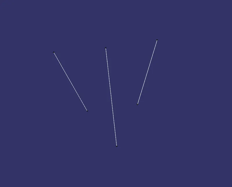
- Thus, the bisector line obtained is the X direction tooling clearing axis.
- Now for Y direction tooling clearing, we take sketch in XZ plane and take intersection of surface body along XZ plane.
- In that we draw a line along the inclined surface of intersection and one more line such that it is 6 degrees to the first line drawn. It will look something like as shown below. Turn the first line to construction as it may not be required later on.
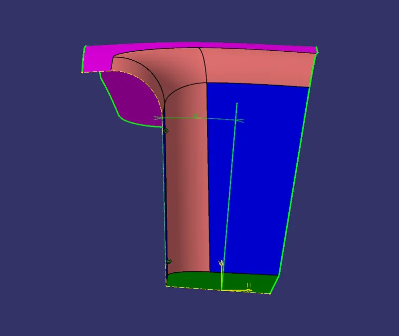
- Thus, the line obtained is the Y direction tooling clearing axis.
- Now, we create a line by bisecting these 2 lines (X and Y direction tooling clearing axes). Thus, we obtain the final tooling direction and axis along it.
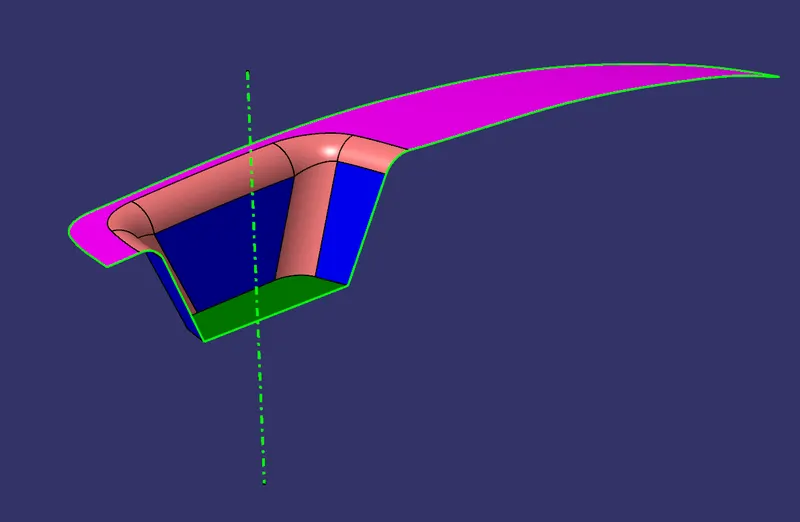
IMAGES
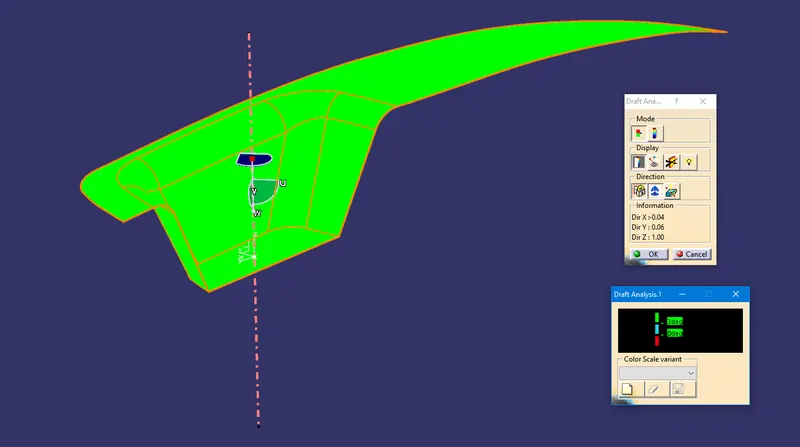
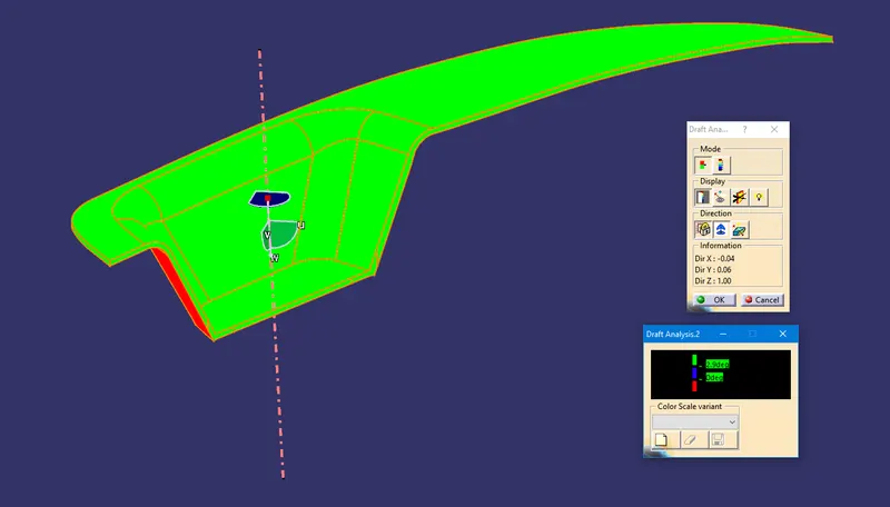
Draft Analysis and color scale variant
Class A Surface
Solid Body
Core and Cavity Blocks Design:
- Taking the Class-A surface as top surface and class B and C surfaces as shown take a trim to obtain the parting surface with the component surface area.
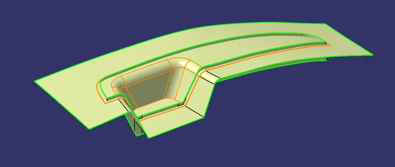
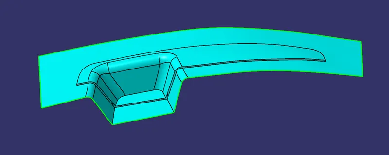
- After getting the whole parting surface we need parting line to obtain the actual parting surface (without component surface area).
- Now, Intersect the class B and class C surface to obtain the parting line as follows.
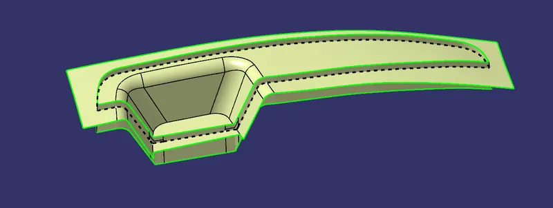
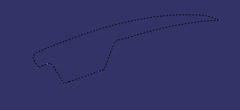
- Now, split the initial parting surface with the parting line, and the resulting surface is the actual parting surface.
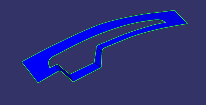
- Now extrude a rectangle as shown below.
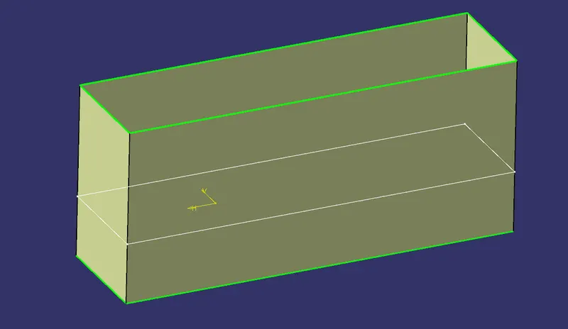
- Then trim the rectangular surface 2 times, as shown below, once with the trim obtained above and then with the class B surface, to get the bottom of core block and top of cavity block.
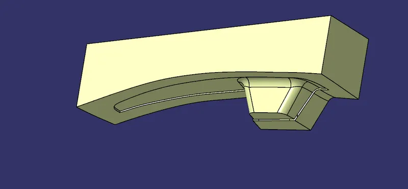
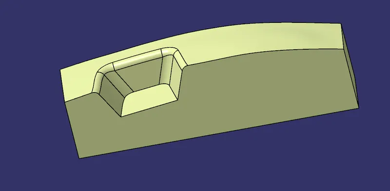
- Fill the top and bottoms of corresponding surface trims and form solid using Closed Surface command.
Model different views
Solid body
Front view
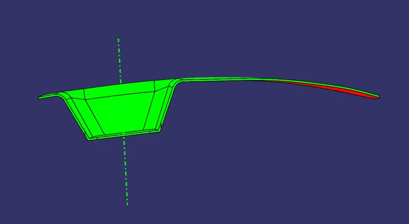
Side view
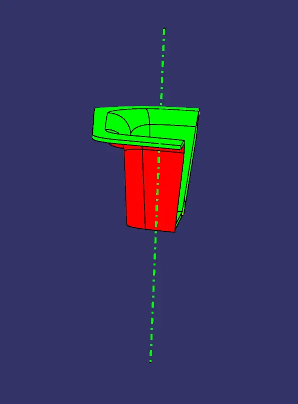
Top view
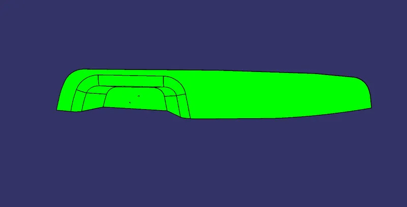
Isometric view
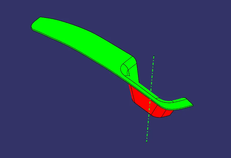
Core Block
Front View
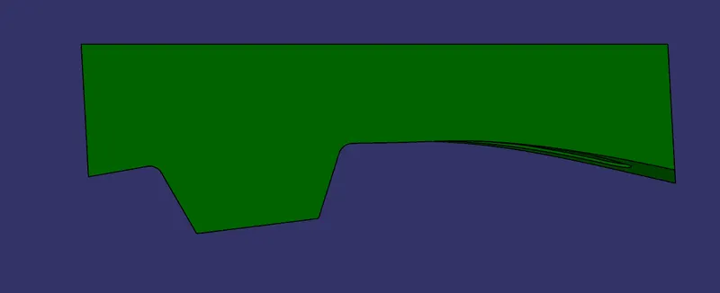
Side View
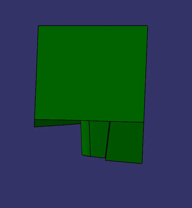
Bottom View
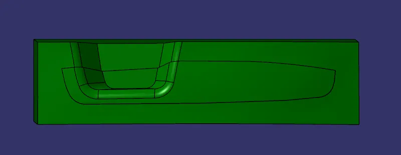
Isometric View
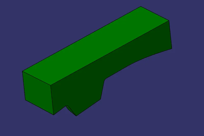
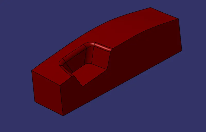
Cavity Block
Front View
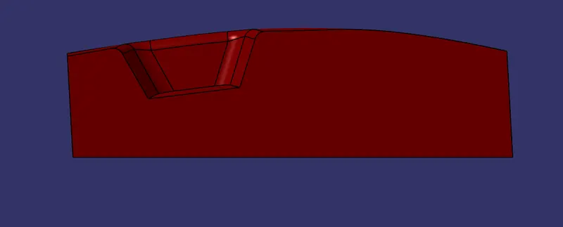
Side View
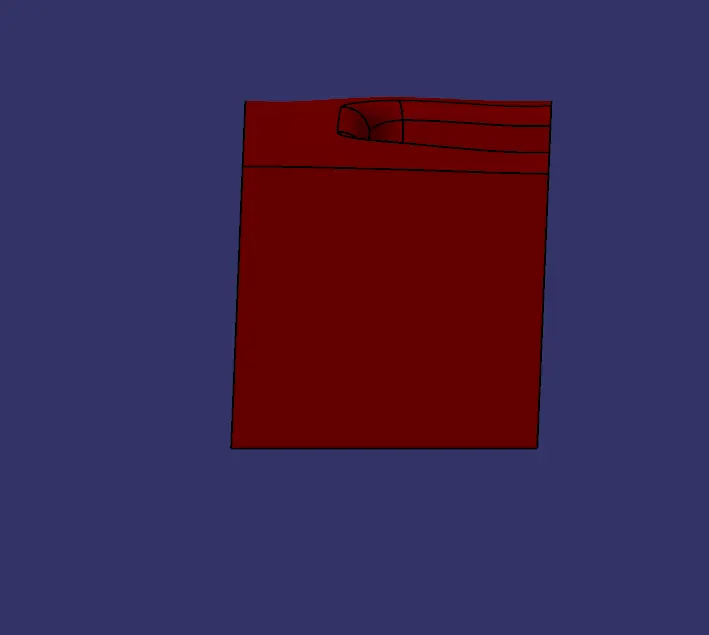
Top View
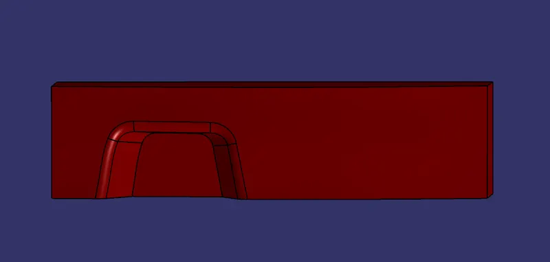
Isometric View
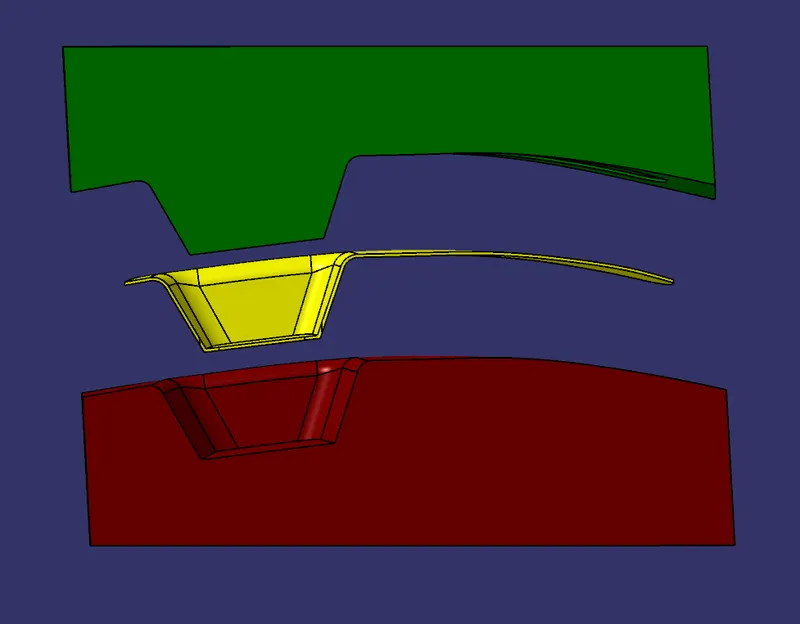
Core and Cavity with Component (Exploded View)
View1
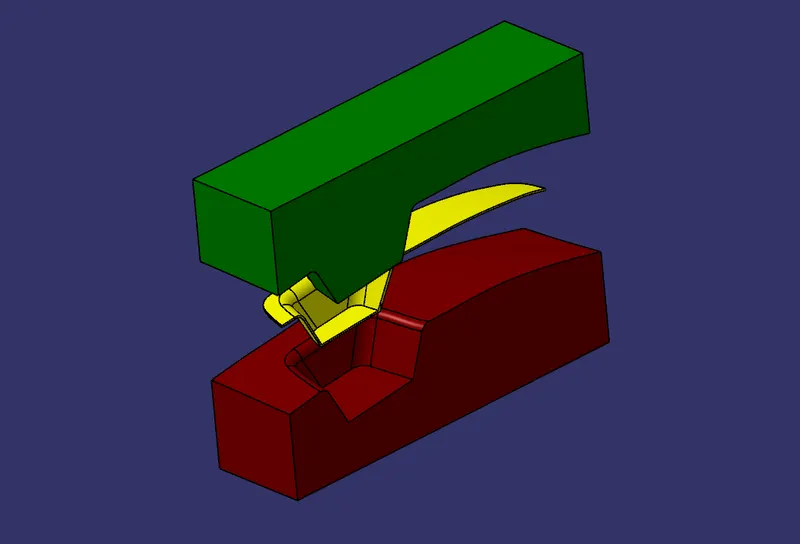
View2
Parting Surface
Parting Line