Week 8 - Challenge 5 - Core & Cavity Design
Parting Line and Parting Surface
Core:
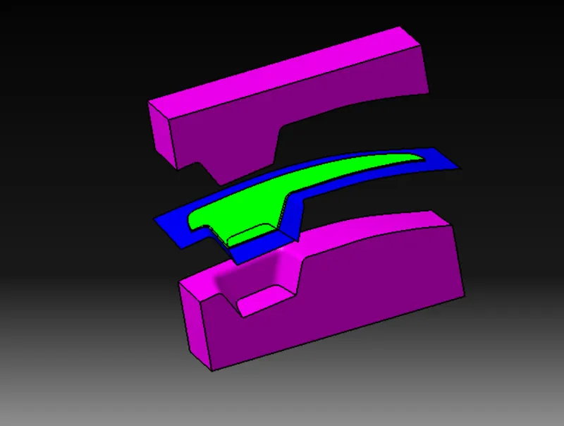
The core is the movable part which forms the internal shape of molding.
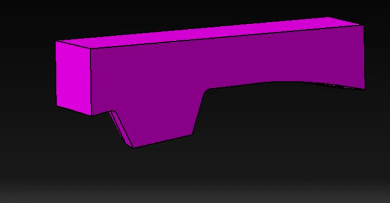
Cavity:
The cavity is fixed part where the plastic material gets filled.It forms the external shape of the product.
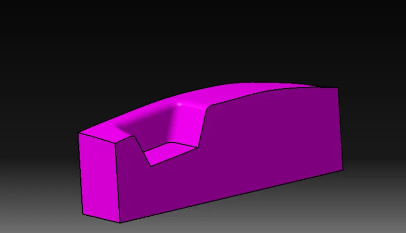
Parting surface:
During injection molding process,the core and cavity are pressed tightly and forms a sealed hollow to avoid the melt flow leakage and maintain certain holding pressure ,the pressured surface is called as parting surface,usually the parting surface are the biggest projection outline of the part.
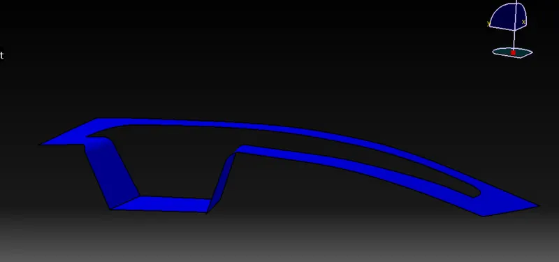
Design parting surface should follow the following principles:
- Design the injection mold structure as simple as possible. Avoid or reduce side parting as much as possible to reduce the complexity of mold making.
- Ease of de-molding. As far as possible, for instance, the plastic parts should stay in fixed halve of the injection mold and ejected by ejection system, avoid side de-molding action.
- Ensure the dimensional accuracy of the molded parts. Try to make the parts with similar dimensional accuracy requirements in the same module to reduce manufacturing and assembly errors.
- Ensure appearance requirement of the molded parts. Flash or mismatch occurs usually on parting surface, so the parting surface should not be designed on any high quality requirement surfaces.
- Ensure adequate venting. If possible, parting surface should be place at the end of the mold flow. This is going to be a good advantage of filling and venting.
Types of parting surface:
- Flat or straight parting surface
- Stepped parting surface
- Angled parting surface
- Complex or porfiled parting surface
Parting line:
Parting line is a area in which the components and parting surface meets or it is a junction between core half,cavity half and parting surface.
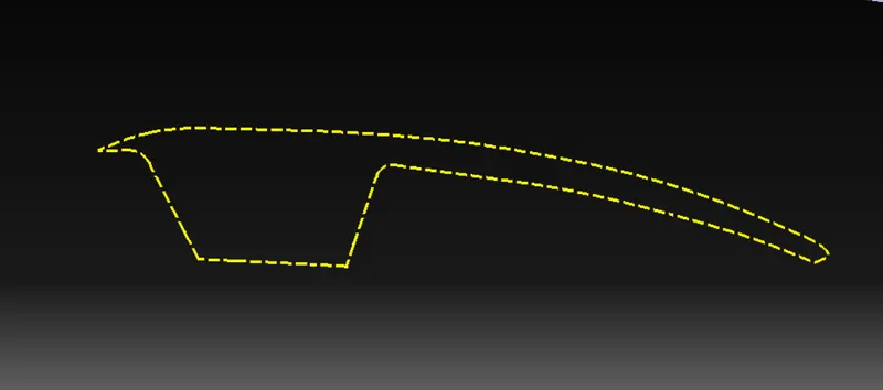
Types of parting lines
Vertical parting line:
The vertical parting line is commonly used. It is a plane perpendicular to the mold opening direction
Stepped parting line:
According to the specific situation of some plastic parts, the parting line is made stepped.
For the stepped parting line, due to the large force on one side of the cavity, the injection eccentric force is generated on both sides of the cavity, which causes the relative sliding tendency between the fixed half and the moving half molds inorder to avoid this stepped parting line is used.
Comprehensive parting line:
This form is based on the needs of the structure of the plastic part, sometimes combining steeped and curved parting lines, or beveled and curved parting line to form a comprehensive parting line
Beveled parting surface:
The shape of the parting line is beveled.
Curved parting line:
The shape of the parting line is curved.
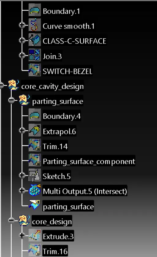
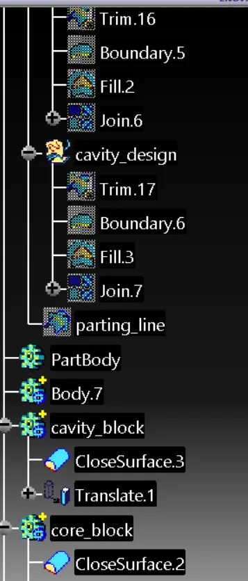
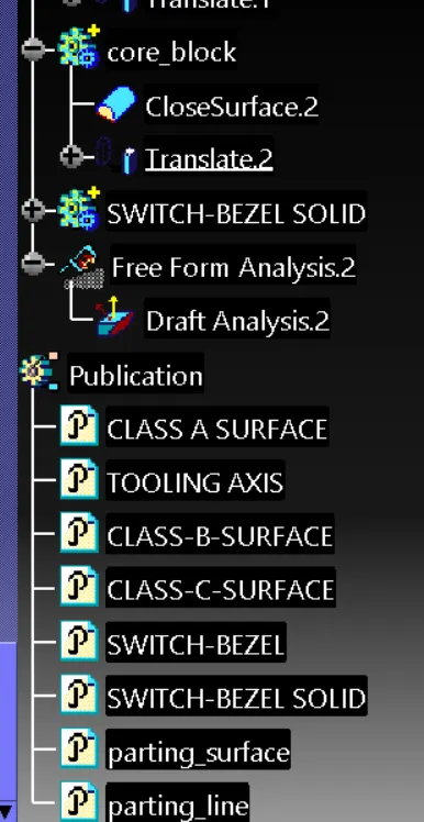
Isometric view:
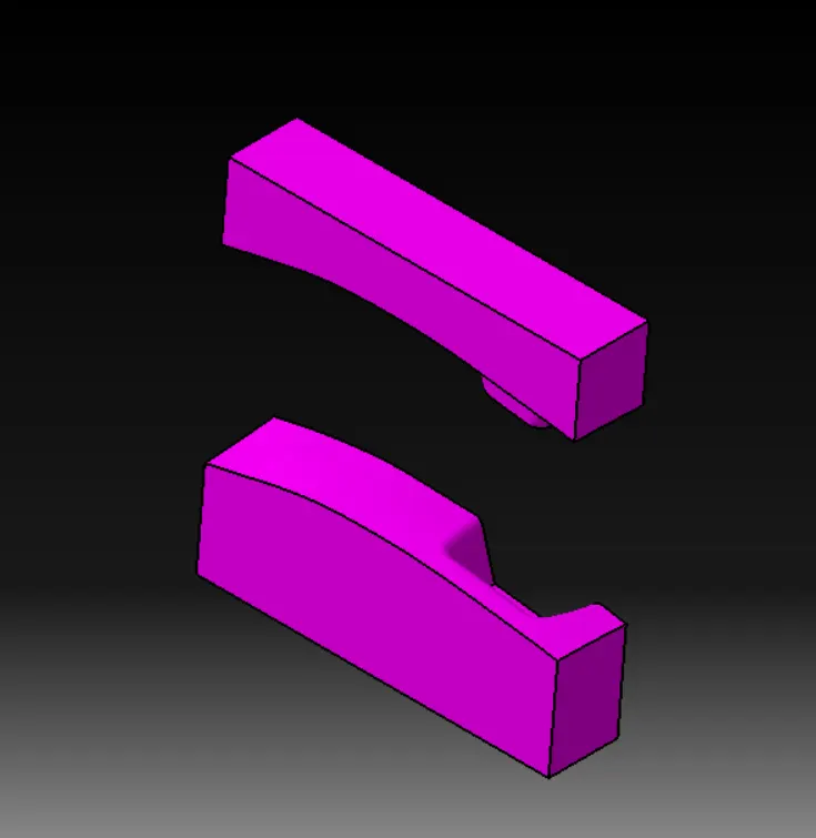
Front view:
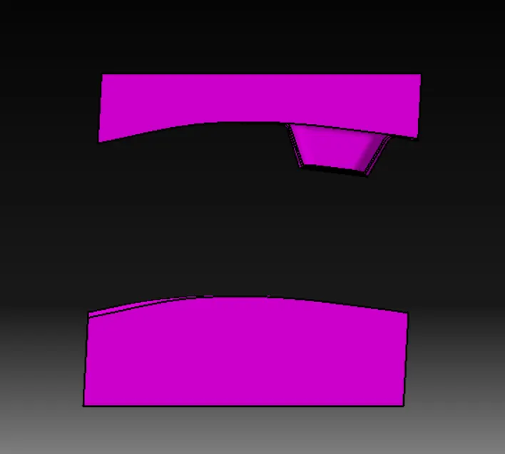
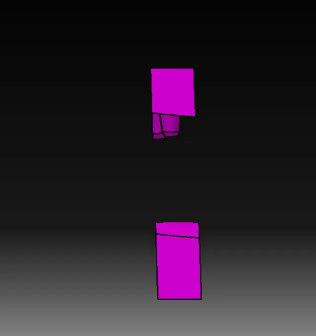
Top view of cavity
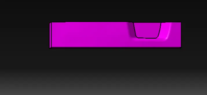
Bottom view cavity:
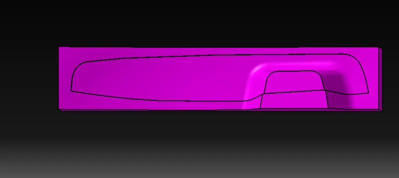
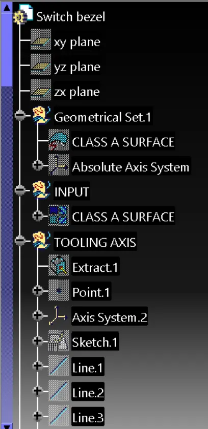
Tooling direction:
The intersection between YZ axis and the surface is taken and then side walls of the intersection is extended and a bisecting line is taken between these side walls.
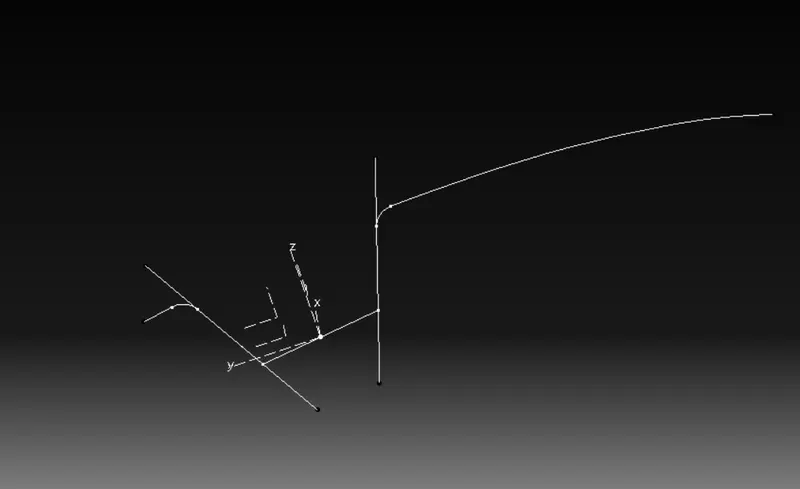
A line is drawn at angle of 5 def in ZX axis with respect to the side walls
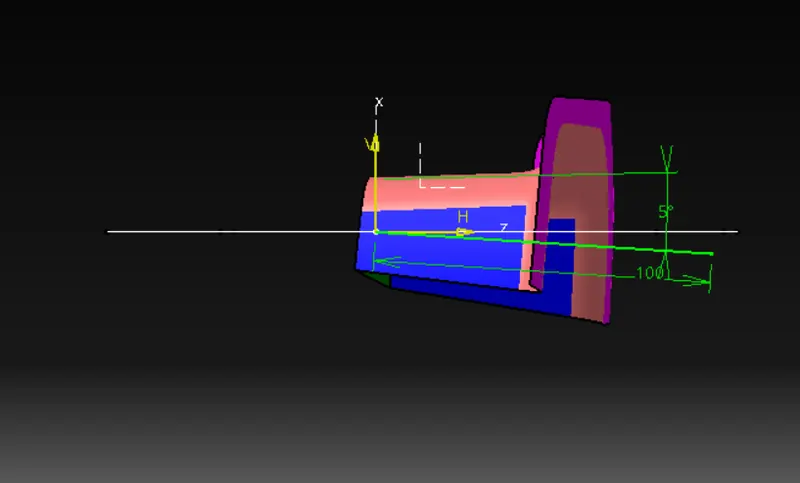
A bisecting line is taken between the above two lines which gives tooling axis
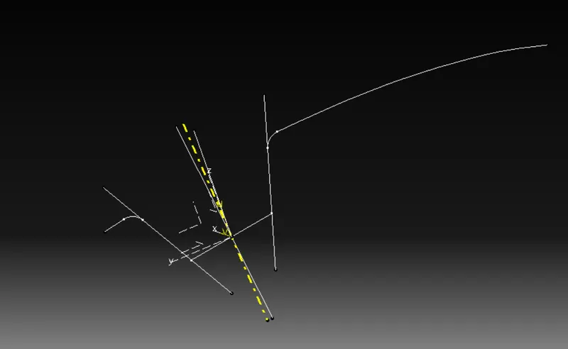
The yellow colour line indicates tooling direction.
Draft analysis:
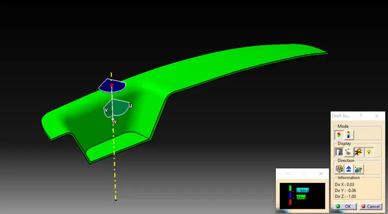
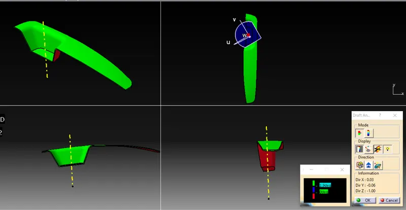
The green colour indicates the draft angle is 2.9 deg
The red colour indicates negative draft ,this part can be manufactured with a draft angle of 2.9 deg with respect to the toolin axis.