Week 8 - Challenge 5 - Core & Cavity Design
DRAFT ANALYSIS
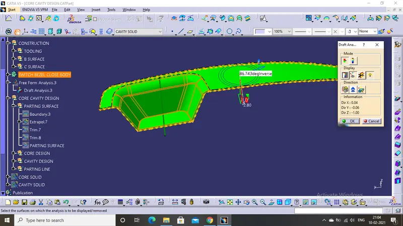
FIG 1.0
The above image (FIG 1.0) shows the draft analysis of switch rest surface with a draft angle of 86.74 degree which clears the nominal draft value of 3 degree and rough patch draft of 7 degree. Hence the part is good to go for manufacturing.
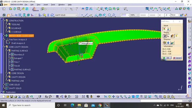
FIG 1.1
The above image (FIG 1.1) shows the draft analysis of door handel with a draft angle of 86.74 degree which clears the nominal draft value of 3 degree. Hence the part is good to go for manufacturing.
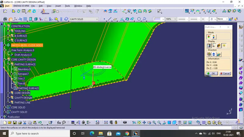
FIG 1.2
The above image (FIG 1.2) shows the draft analysis of base with a draft angle of 85.66 degree which clears the nominal draft value of 3 degree and rough patch draft of 7 degree. Hence the part is good to go for manufacturing.
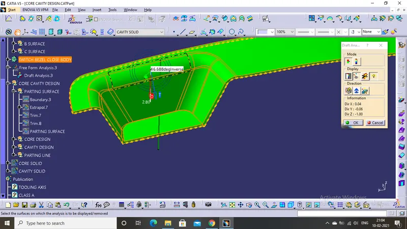
FIG 1.3
The above image (FIG 1.3) shows the draft analysis of door handel inside fillet with a draft angle of 46.68 degree which clears the nominal draft value of 3 degree and rough patch draft of 7 degree. Hence the part is good to go for manufacturing.
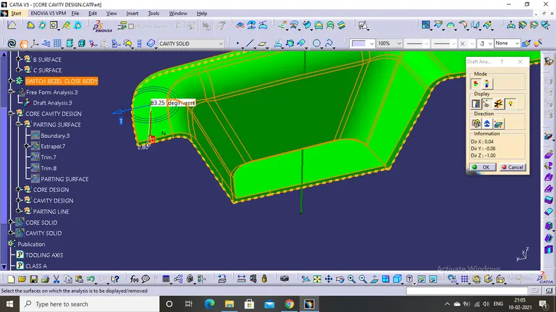
FIG 1.4
The above image (FIG 1.4) shows the draft analysis of switch rest surface car backwaed with a draft angle of 83.25 degree which clears the nominal draft value of 3 degree and rough patch draft of 7 degree. Hence the part is good to go for manufacturing.
*****************************************************************************************************************************************************
TOOLING AXIS
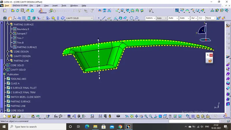
TOOLING AXIS is shown in the above image in white colour and it is created by using two tooling axis one in X direction and one in Y , with help of X&Y tooling the bisecting line is created with an angle of 3 degree with the help of command in line option. The purpose of bisecting line is to give a draft angle to core and cavity . Core and cavity will be shown in the fig below.
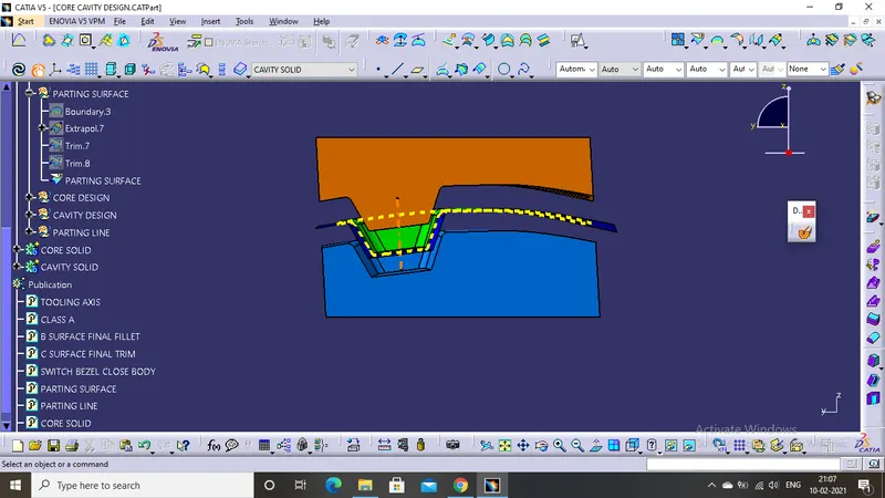
Amber colour shows the CORE side and blue colour shows the CAVITY side in middle parting line and parting surface with part is shown.
*****************************************************************************************************************************************************
PARTING SURFACE AND PARTING LINE
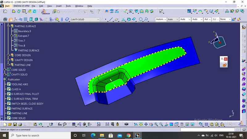
BLUE colour surface is the parting surface it divides the core and cavity . It is noting but the B SURFACE it is thin paper line surface which also helps in creating the thickness of the component.
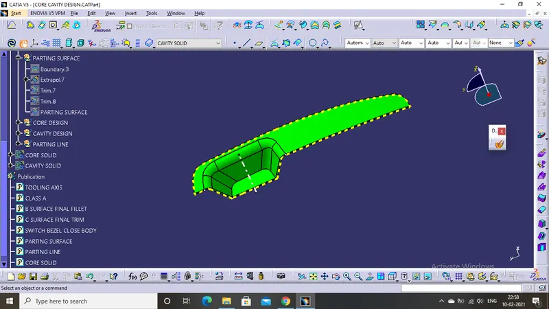
YELLOW colour line is the parting line it divides the parting surface with the main component and allow the material to properly fit into the material .
*****************************************************************************************************************************************************
DIFFERENT VIEWS
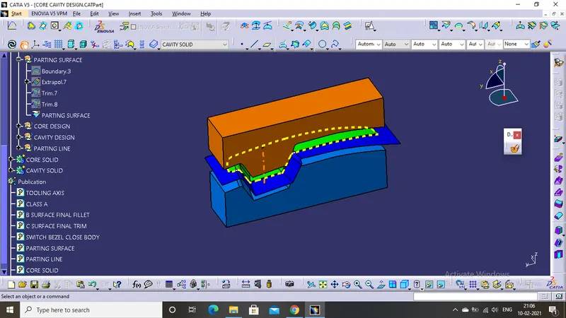
ISOMETRIC VIEW
FRONT VIEW
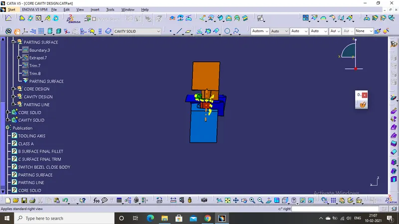
SIDE VIEW
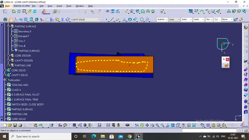
TOP VIEW