Week 8 - Challenge 5 - Core & Cavity Design
CORE & CAVITY for SWITCH BEZEL DESIGN
Objective:
The main objective is to develop Design of Core & Cavity blocks for an Automotive Plastic Component – Door Switch Bezel using industry principles such as Parting Surface and Parting Line definition, draft angle, Draft Analysis, determining and implementing of Tooling Axis, Class A, Class B, Class C surfaces and maintaining the thickness of the part at 2.5 mm. The Molds are designed using surface design and Solid Design techniques in Catia V5 application.
Introduction:
Parting Surface:
- Generally, Injection Molding has 2 major components: The Movable Half and The Fixed Half.
- During Injection Molding Process, these 2 halves are pressed together tightly to form a sealed hollow to avoid the melt flow leakage and maintain certain holding pressure.
- The pressed surface is called the Parting Surface.
- Usually, the parting surface are the biggest projection outline of the part.
- Parting Surface directly affects the Product Quality, Ease of Construction and Operation of the Injection of the Mold, The Mold Design is one of the key factors to the success.
Design of Parting Surface should follow the following Design Principles:
- Designing the Mold Structures as simple as possible.
- Avoid or reduce side parting as much as possible to reduce complexity of mold making.
- Ease of De-Molding. The plastic component must stay at the fixed half in most cases and ejected by the ejection system and avoid side De-Molding action.
- Ensure dimensional accuracy of the molded parts and try to make parts with similar dimensional accuracy requirements in the same module to reduce manufacturing and assembly errors.
- Ensure appearance requirement of the molded parts.
- Flash or mismatch usually occurs on the parting surface, so it should not be designed on a High-quality requirement surface.
- Ensure adequate venting or De-gassing. If possible, Parting Surface should e placed at the end of the Mold Flow. This can be good advantage for Filling and Venting.
Parting Line:
- Intersection of the Plastic component with the Parting Surface is called the Parting Line.
- It is the Bordered Outline of the component along the Parting Surface.
Draft Angle:
- Draft is an angular tapering given at the design stage to every Plastic component that has to be manufactured.
- It is given in the direction of the Mold Movement.
- The draft allows the parts to release easily from the mold without creating friction between the surface of component and the core and cavity plates.
- When a Plastic component cools down inside the mold, the natural tendency of it is to shrink and attach to the core or cavity half.
- The movement of mold opening causes friction on the walls of the component as well as the core/cavity blocks.
- This reduces the life of the mold as well as the component itself.
- The component may also have rough surface finish as well as weak structure due to this method.
- This problem can be solved by giving draft to the component.
- Most applications require minimum draft angles of around 0.5⁰ to 1⁰, however 3⁰ draft angles are widely accepted for cost saving purpose.
- 7⁰ Draft angles are given to textured surfaces like Instrument Panels.
- Minimum possible draft angles are given to screw bosses, ribs and stiffeners due to their critical nature.
- Walls having 0⁰ or negative draft are difficult to manufacture thus, are required to redesign from the Class A stage.
Tooling Axis:
- Tooling Axis is the direction in which the mold opens and closes.
- Part Drafts are given along this axis.
Draft Analysis:
- Draft Analysis is a tool in Catia which identifies the zones which deviates from the specified values of angles along a defined draft direction using colour codes.
- It highlights the region of draft using colours.
- Draft Analysis is the first step performed after receiving the Class A of the component.
- Draft analysis should be passed in order to make the plastic component manufacturable.
- Acceptable draft angles are used as range for draft analysis.
Class A Surface:
- In automotive design, a class A surface is any of a set freeform surfaces of high efficiency and quality. It is the visible aesthetic surface of any automotive component.
- Class A surface refers to those surfaces which are visible and abide to the physical meaning, in a product.
- This classification is primarily used in the automotive and increasingly in consumer goods industry.
- It is a requirement where aesthetics has a significant contribution.
- For this reason, the exterior of automobiles is deemed Class A.
Class B Surface:
- Class B surfaces are engineering surfaces which are invisible to the eyes or often on the back side of the Class A surfaces.
- It is mainly the thickness of the component or Class A.
- These surfaces need to be designed as per the Class A surface i.e., the continuity, thickness of the component, functionality etc should be maintained.
- These surfaces include the main engineering features such as Screw bosses, Ribs, Stiffeners and fixations.
- B surfaces also do not contain any aesthetic styling content and textures since it is not visible to eyes.
Class C Surface:
- Class C surfaces are connectors between Class A and Class B surfaces.
- This surface connects both A and B surfaces along or angled to the Tooling Axis.
- It contains the draft as per the design.
- It is basically the thickened surface between both A and B surface.
Design Methodology:
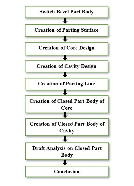
The design methodology of Core & Cavity for Switch Bezel is explained through flow charts.
Description:
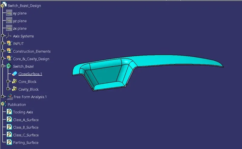
Switch Bezel Part Body:
- For creating Core & Cavity for switch bezel design component, the closed part body is need to be created from the Class A surface.
- This Switch Bezel Part Body is already created before with under gone procedures like Creating Draft angle, Tooling Axis, Class B, Class C surfaces and Closed part body.
- The Switch Bezel Part body is shown in below image.
Creation of Parting Surface:
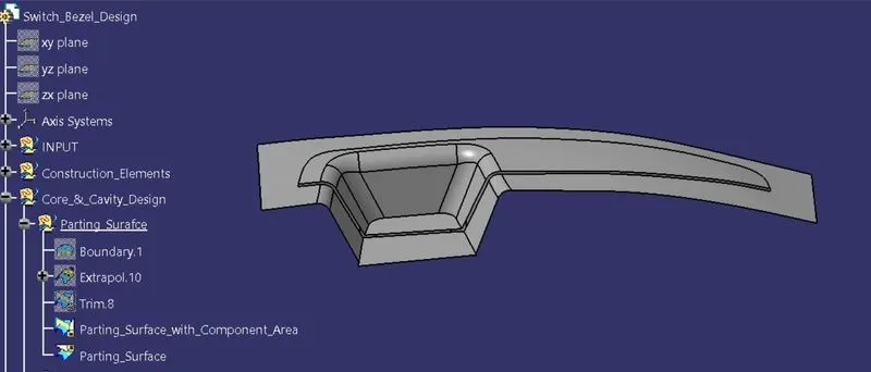
- For creating Parting Surface, Boundary, Extrapolate, Trims and Split commands were used.
- For extrapolating the Class-A surface, need to create boundary on Class A surface.
- Extrapolate the boundary at the length of 11 mm and click Ok to validate.
- Then click on Trim option, the dialog box appears in that select extrapolate and Class C surface and click ok to validate.
- Then Trimmed surface as named as Parting Surface with component area.
- And then Parting surface is created with split command. By clicking on the split command, the dialog box appears in that select Parting surface with component area and select Parting line to create Parting surface.
- The Parting Surface as shown in below image.
Creation of Core Design:
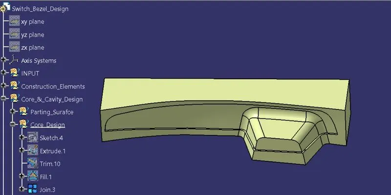
- Create a new sketch with respect to already created Axis system in that select XY Plane and select existing point and swap the position of horizontal and vertical arrows as per the requirement and click Ok to start the sketch.
- Select Rectangle option to create rectangle which covers the switch bezel part body and providing dimensions to the sketch to make sketch constrained and click Exit sketch.
- Clicking on the Extrude command, the dialog box appears in that select Profile as Sketch, Direction as Tooling Axis, Limit 1 as 125 mm, Limit 2 as 70 mm and Click Ok to validate.
- Then Clicking on the Trim Command, the dialog box appears in that select Extrude and Parting surface with component area and click Ok to validate.
- Clicking on the Fill surface Definition option, the dialog box appears in that select Boundary box right click in that box to select create new boundary option and click on the edge of the open surface to close the surface.
- And use Join option to join discontinuity surfaces to make solid part body.
- The Core Design is shown is below image.
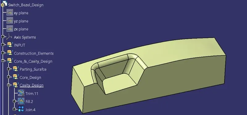
Creation of Cavity Design:
- For Creating Cavity Design, Same procedures were carried out as Core design. Only parameters were changed.
- The Cavity Design is shown in below image.
Creation of Parting Line:
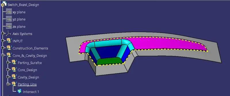
- For creating Parting Line, Intersection command is used.
- Clicking on the Intersection command, the dialog box appears in that select First element as Class B surface and select Second element as already created Trim.6 surface and click Ok to validate.
- Now the Parting line is created and thickening the line, changing Yellow colour to the line to be highlighted as shown in below image.
Creation of Closed Part Body of Core:
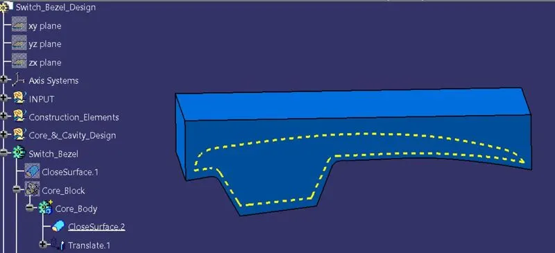
- Insert new Part Body and name it as Core Block.
- Switching to Part Design Workbench in that Click on Close surface definition, the dialog box appears in that select Core design surface and click Ok to validate.
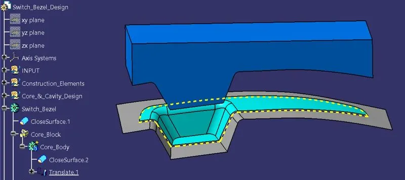
- And Click on Translate Definition command, the dialog box appears in that select Closed Core Block, Direction as Tooling Axis, Distance as 90 mm and Click Ok to validate.
- The closed Part Body of Core is shown in below image.
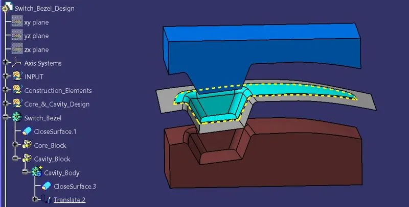
Translate of Core Part Body:
Creation of Closed Part Body of Cavity:
- Insert new Part Body and name it as Cavity Block.
- Switching to Part Design Workbench in that Click on Close surface definition, the dialog box appears in that select Cavity design surface and click Ok to validate.
- And Click on Translate Definition command, the dialog box appears in that select Closed Cavity Block, Direction as Tooling Axis, Distance as -90 mm and Click Ok to validate.
- The closed Part Body of Cavity is shown in below image.
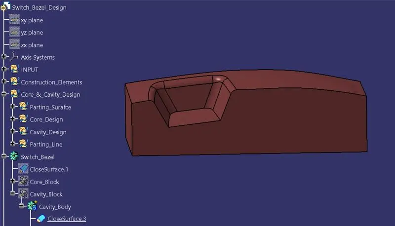
Translate of Cavity Part Body:
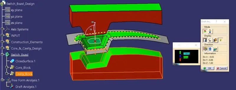
Draft Analysis on Closed Part Body:
- Change View Mode Customization to Material mode.
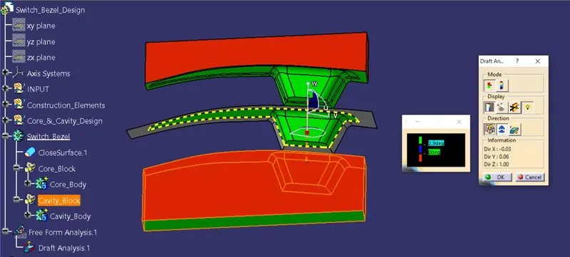
- Clicking on Insert Tab, selecting Analysis and then select Feature draft analysis and drag the compass to the tooling axis and lock the compass position.
- Then click on the closed part body, to check the part whether its clearing all required faces on respective Tooling Axis that as created.
- The Core & Cavity for Switch Bezel is passing the draft analysis as shown in below image.
Draft Analysis:
Standard Views:
Front View:
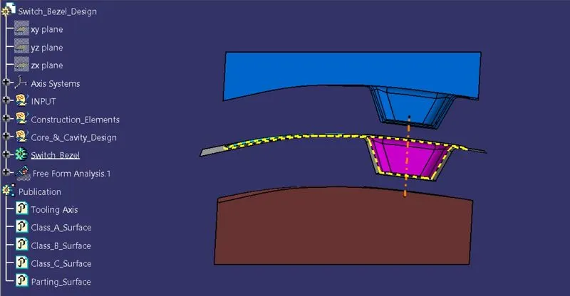
Back View:
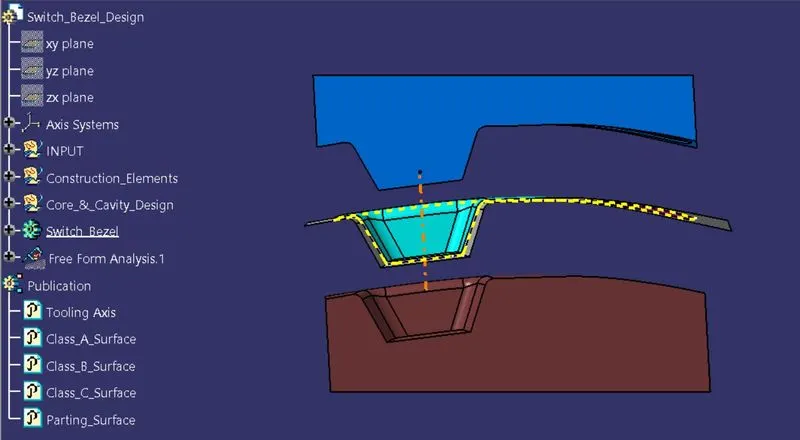
Left Side View:
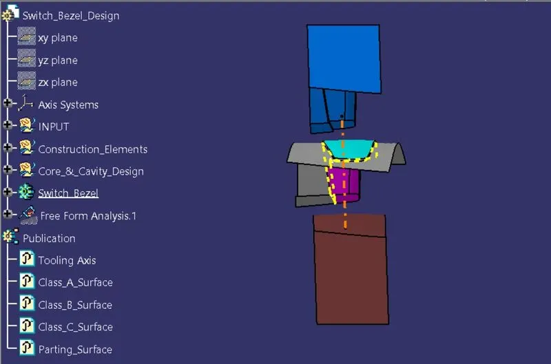
Right Side View:
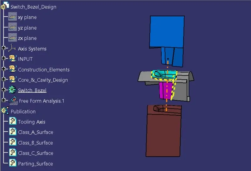
Top View:
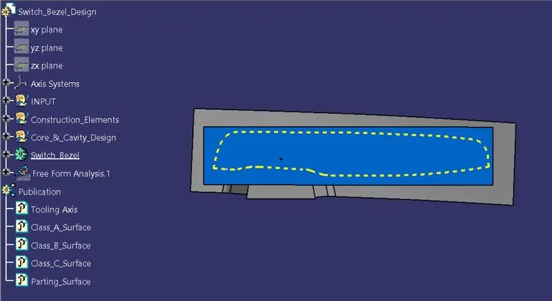
Bottom View:
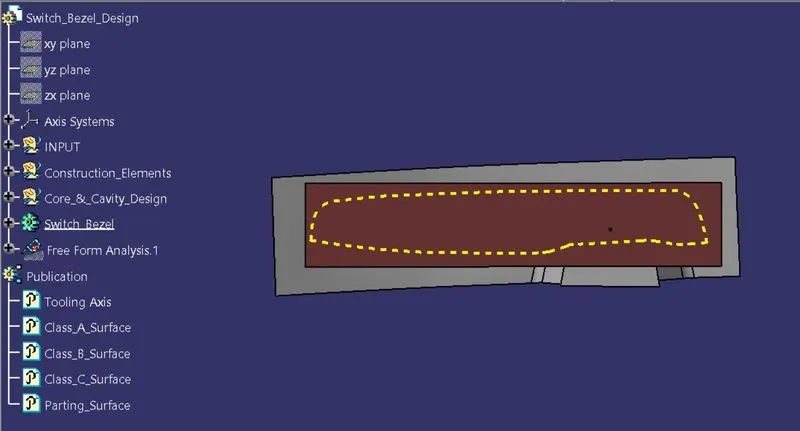
Isometric View:
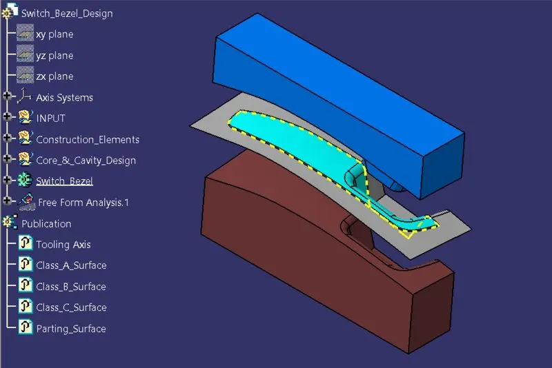
Conclusion:
Successfully created the design of Core & Cavity for the Mold of Automotive Plastic Component – Switch Bezel using concepts of Parting surface, Parting Line, Draft angle, Draft Analysis for Class A and Final enclosed Surface, Tooling Axis creation and implementation, Class B & Class C creation and Conversion to a Solid Part maintaining the part thickness at 2.5 mm.