Advanced Sheet Metal Design Using NX Cad Challenge_7_ Metal bracket-II
Creating Metal Bracket-II from 2D
Objective:
The main objective is to design a Metal Bracket-II from 2D drawing using Siemens Nx application.
Introduction:
Here, we are going to study about how to create metal bracket-II from 2D drawing in siemens Nx Sheet metal Application. Using this application, how we are going to use tools step by step to complete the design. Then detailed explanation about tools used to make solid models and their features.
Design Methodology:
The steps involved in creating metal bracket-II from 2D drawing are explained through flow charts.
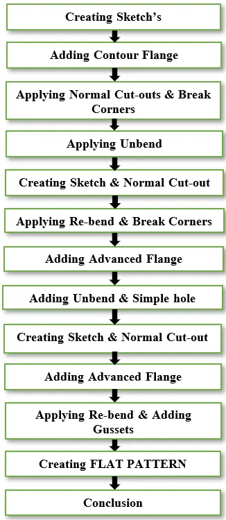
Description:
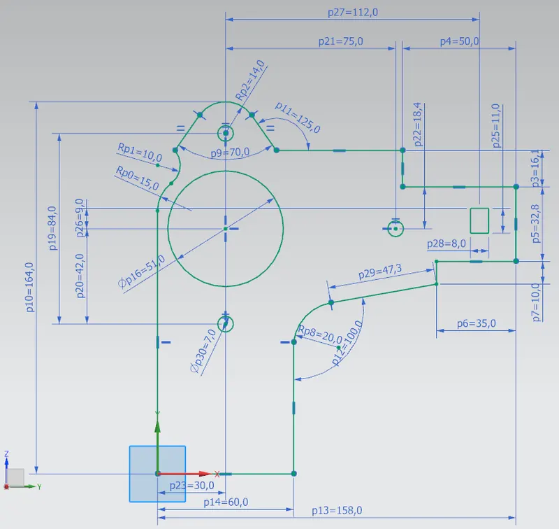
1.Sketching on YZ Plane:
- Start Nx 11 and create a new sheet metal model called Creating Metal Bracket-II from 2D drawing.
- Creating a sketch in YZ plane and drawing a line, curves as per the given 2D drawing.
- Applying Geometric constraints to the sketch wherever necessary.
- Applying dimensions as per the given 2D drawing.
- Creating circles & rectangle as per the drawing and positioning with horizontal & vertical constraints.
- Attaching sketch view image for the reference.
Sketch View 1:
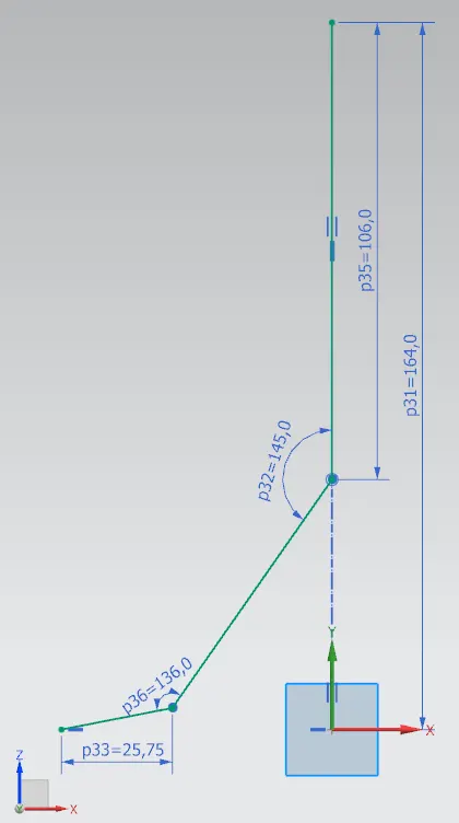
2.Sketching on XZ Plane:
- Creating a sketch in XZ plane and drawing a line as per the given 2D drawing.
- Applying Geometric constraints to the sketch wherever necessary.
- Applying dimensions as per the given 2D drawing.
- Attaching sketch view image for the reference.
Sketch View 2:
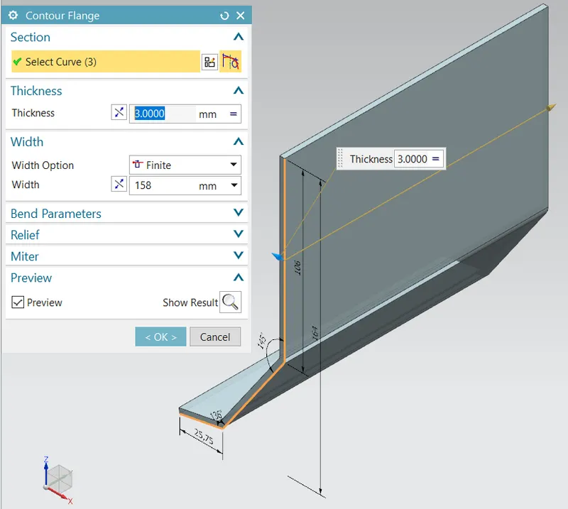
3.Adding Contour Flange:
- Adding contour flange to drawn sketch in XZ plane.
- Clicking on contour flange tab, select drawn sketch to add flange with thickness of 3 mm and 158 mm width. Then click ok to validate.
Contour Flange View:
4.Applying Normal Cut-outs & Break Corners:
- Clicking on the Normal cut-out tab, to create cut-out on the part.
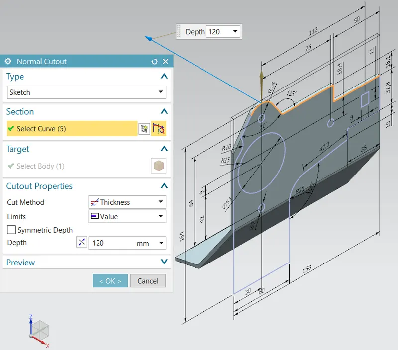
- In Normal cut-out dialog box, selecting drawn sketch and providing cut-out properties as cut method as thickness, limits as value, depth of 120 mm. Refer below image
Normal Cut-out View 1:
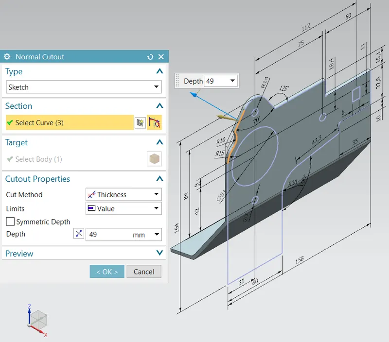
- In Normal cut-out dialog box, selecting drawn sketch and providing cut-out properties as cut method as thickness, limits as value, depth of 49 mm. Refer below image
Normal Cut-out View 2:
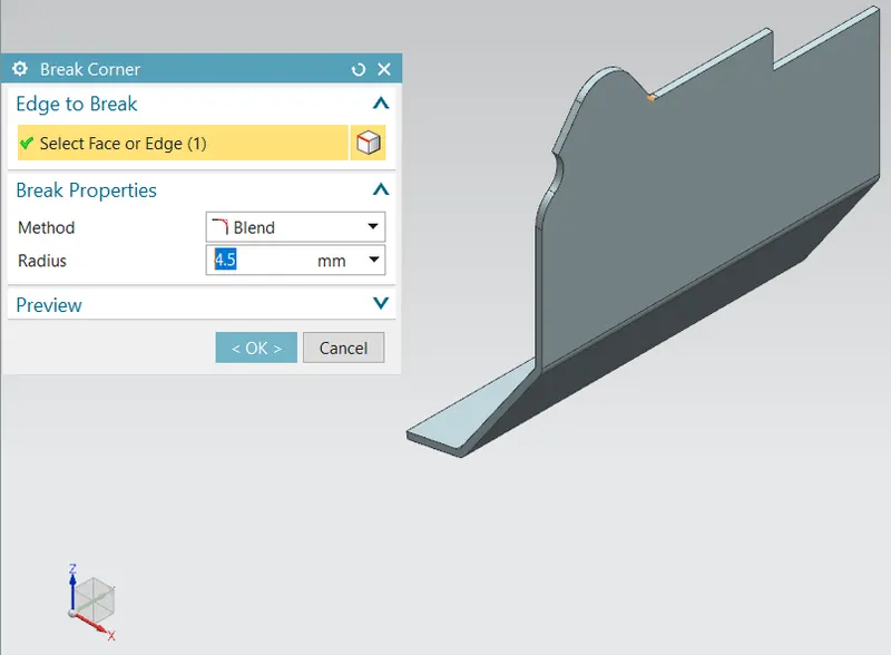
- In Break Corner dialog box, selecting edge to blend 4.5 mm radius as shown in below image.
Break Corner View 1:
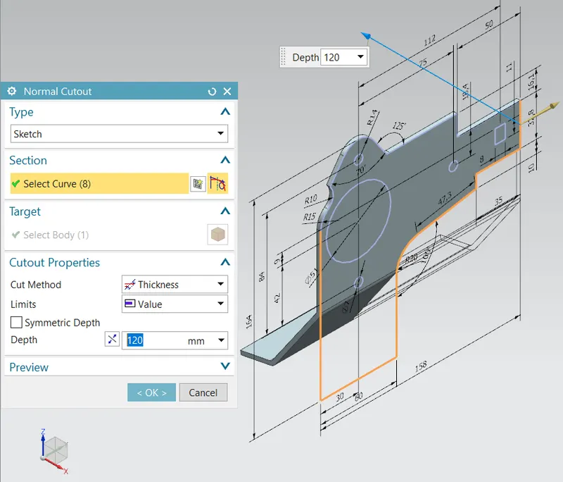
- In Normal cut-out dialog box, selecting drawn lines and providing cut-out properties as cut method as thickness, limits as value, depth of 120 mm as shown in below image.
Normal Cut-out View 3:
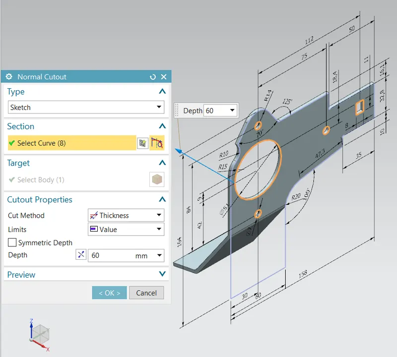
- In Normal cut-out dialog box, selecting drawn circles, rectangle and providing cut-out properties as cut method as thickness, limits as value, depth of 60 mm as shown in below image.
Normal Cut-out View 4:
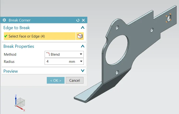
- In Break Corner dialog box, select edges in rectangle to blend 4 mm radius as shown in below image.
Break Corner View 2:
5.Applying Unbend:
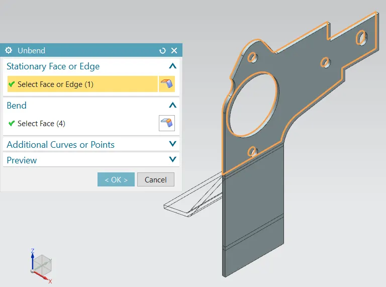
- Clicking on the Unbend tab, to make the part as sheet.
- In Unbend dialog box, selecting stationary face and bends to unbend the bend areas.
Unbend View 1:
6.Creating Sketch & Normal Cut-out:
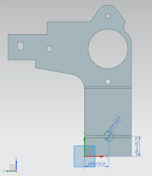
- Creating sketch on the Top of YZ plane.
- Creating a circle on the top surface with respect to the origin, x-directional length of 31 mm, y-directional length of 25.75 mm and circle diameter of 12.5 mm as shown in below image.
- Exiting the Sketch Mode.
Sketch View 3:
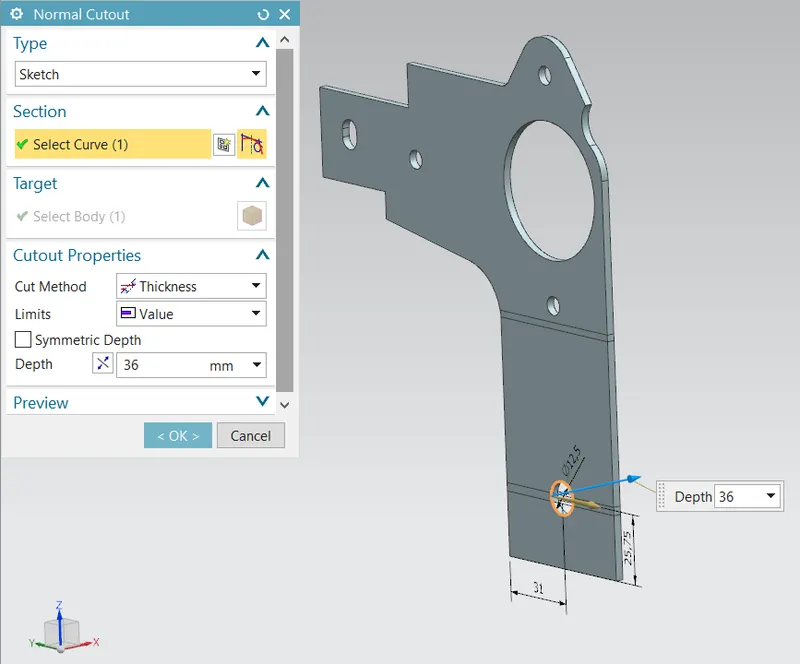
- Clicking on the Normal cut-out tab, to create cut-out on the part.
- In Normal cut-out dialog box, selecting drawn sketch and providing cut-out properties as cut method as thickness, limits as value, depth of 36 mm as shown in below image.
Normal Cut-out View 5:
7.Applying Re-bend & Break Corners:
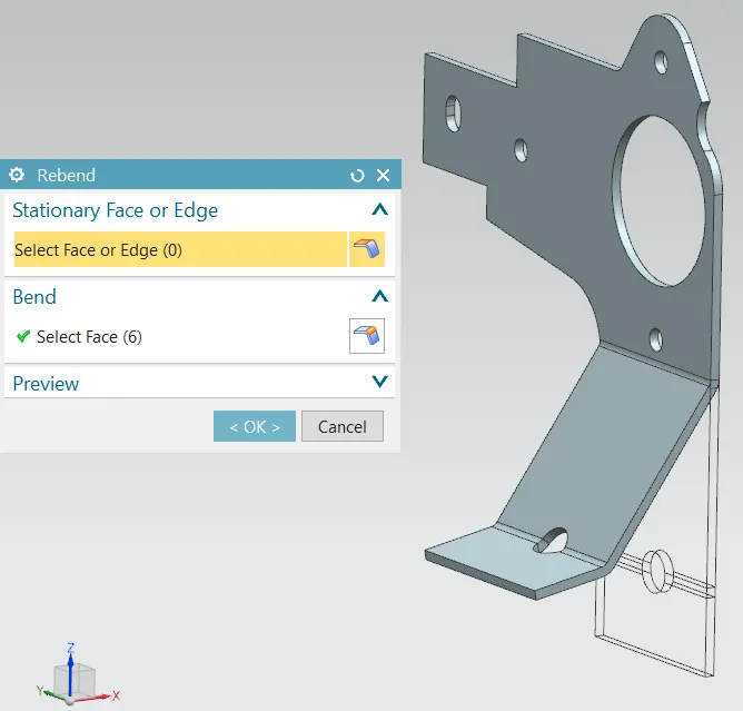
- Clicking on the Re-bend tab, to make part to its original state.
- In Re-bend dialog box, selecting stationary face and bends to re-bend the flat areas to its original position as shown in below image.
Re-bend View 1:
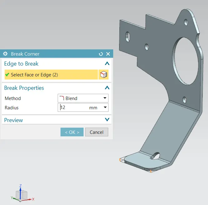
- In Break Corner dialog box, select edges to blend 12 mm radius as shown in below image.
Break Corner View 3:
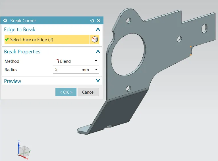
- In Break Corner dialog box, select edges to blend 5 mm radius as shown in below image.
Break Corner View 4:
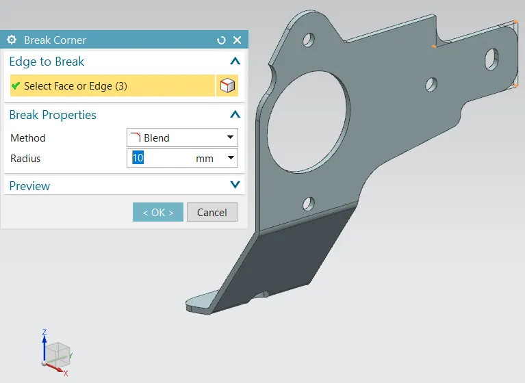
- In Break Corner dialog box, select edges to blend 10 mm radius as shown in below image.
Break Corner View 5:
8.Adding Advanced Flange:
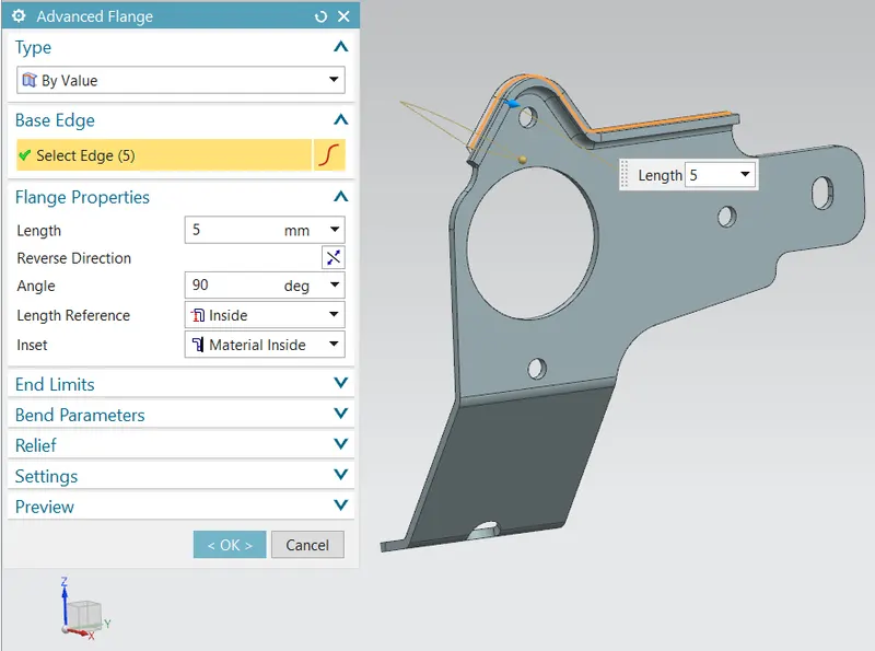
- Clicking on the Advance flange tab, selecting the required edges to add flange with 5 mm length, 90-degree angle as shown in below image.
Advance Flange View 1:
9.Adding Unbend & Simple Hole:
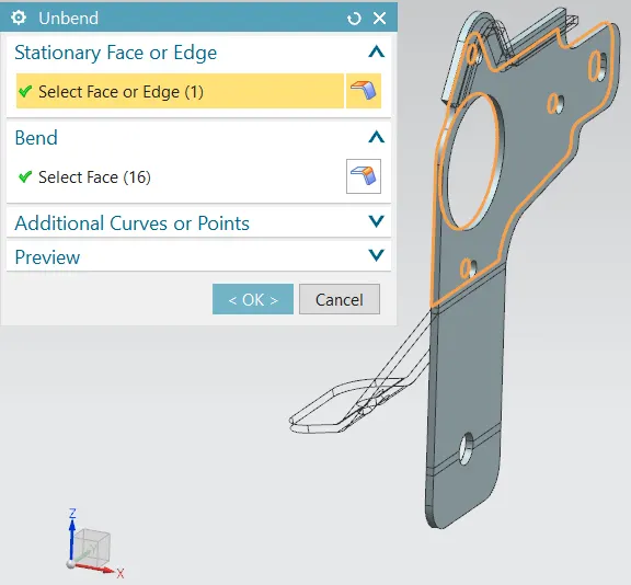
- Clicking on the Unbend tab, to make the part as sheet.
- In Unbend dialog box, selecting stationary face and bends to unbend the bend areas.
Unbend View 2:
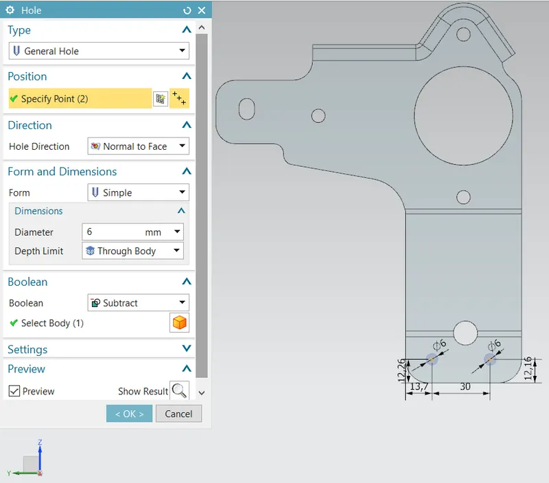
- Clicking on the Hole feature, to make simple holes on the part.
- In hole feature dialog box, click on sketch option to draw circles on the top surface of the part.
- Clicking on circle tab button, draw a circle of 6 mm diameter near to the origin to the distance of 13.7 mm x-direction and the distance of 12.26 mm y-direction.
- Again, drawing another circle with same diameter and different height distance of 12.16 mm from origin.
- Distance between two circles are 30 mm.
- Exiting the sketch mode. Once the sketch is fully constrained.
- After exiting it comes back to hole feature mode, select hole type as general hole, select holes position by clicking on centre point of holes, select form as simple, diameter of 6 mm, depth limit as through body, Boolean as subtract and click ok to validate.
Simple Hole View:
10.Creating Sketch & Normal Cut-out:
- Creating sketch on the Top of YZ plane.
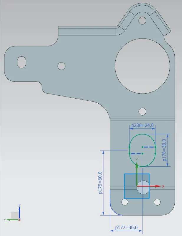
- Creating a slot shape sketch on the top surface with respect to the end line of part, x-directional length of 30 mm from end line to mid-point, y-directional length of 60 mm from end line to mid-point, width of 24 mm and height of 30 mm as shown in below image.
- Exiting the Sketch Mode.
Sketch View 4:
- Clicking on the Normal cut-out tab, to create cut-out on the part.
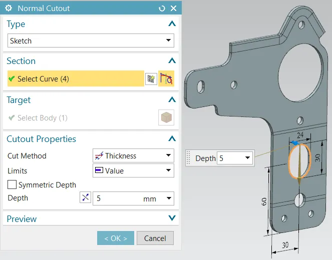
- In Normal cut-out dialog box, selecting drawn sketch and providing cut-out properties as cut method as thickness, limits as value, depth of 5 mm as shown in below image.
Normal Cut-out View 6:
- Clicking on the Normal cut-out tab, to create cut-out on the part.
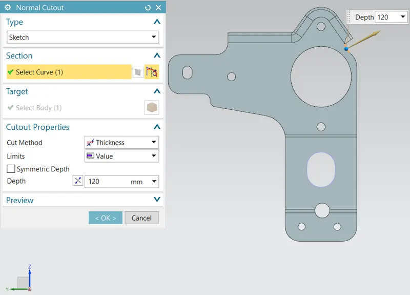
- In Normal cut-out dialog box, selecting existing curve and providing cut-out properties as cut method as thickness, limits as value, depth of 120 mm as shown in below image.
Normal Cut-out View 7:
11.Adding Advanced Flange:
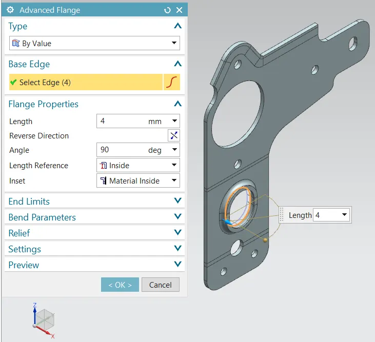
- Clicking on the Advance flange tab, selecting the required edges to add flange with 4 mm length, 90-degree angle as shown in below image.
Advance Flange View 2:
12.Applying Re-bend & Adding Gussets:
- Clicking on the Re-bend tab, to make part to its original state.
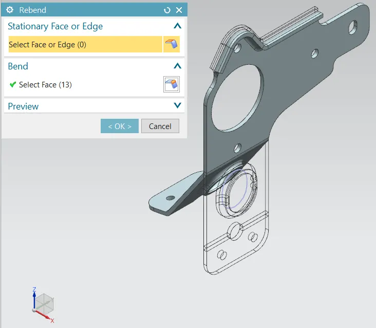
- In Re-bend dialog box, selecting stationary face and bends to re-bend the flat areas to its original position as shown in below image.
Re-bend View 2:
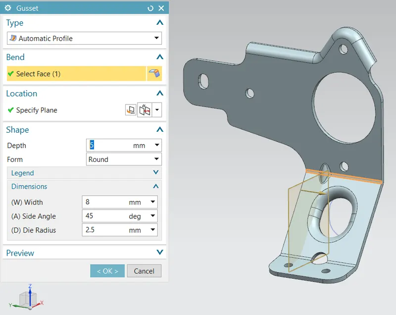
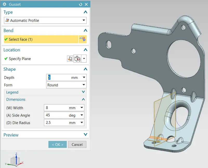
- Clicking on the Gusset tab, to make the part strong at bends.
- In Gusset dialog box, selecting face and specifying plane to the distance of 15 mm right-side, selecting shape form as round, depth as 5 mm and providing dimensions of 8 mm width, angle of 45-degree and die radius of 2.5 mm. Then click ok to validate as shown in below image.
Gusset View 1:
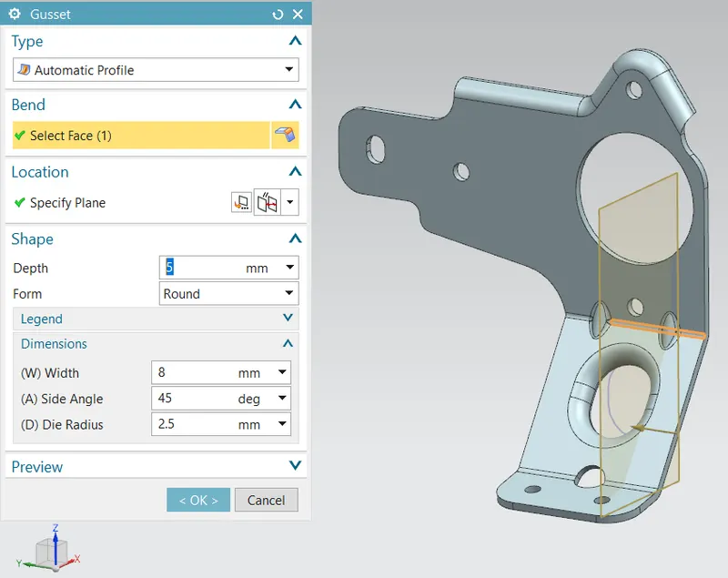
- Redoing the above procedure to complete the gussets adding to the part to make bracket stronger.
Gusset View 2:
Gusset View 3:
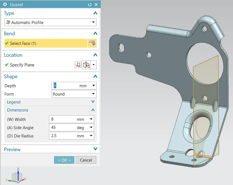
Gusset View 4:
13.Creating FLAT PATTERN:
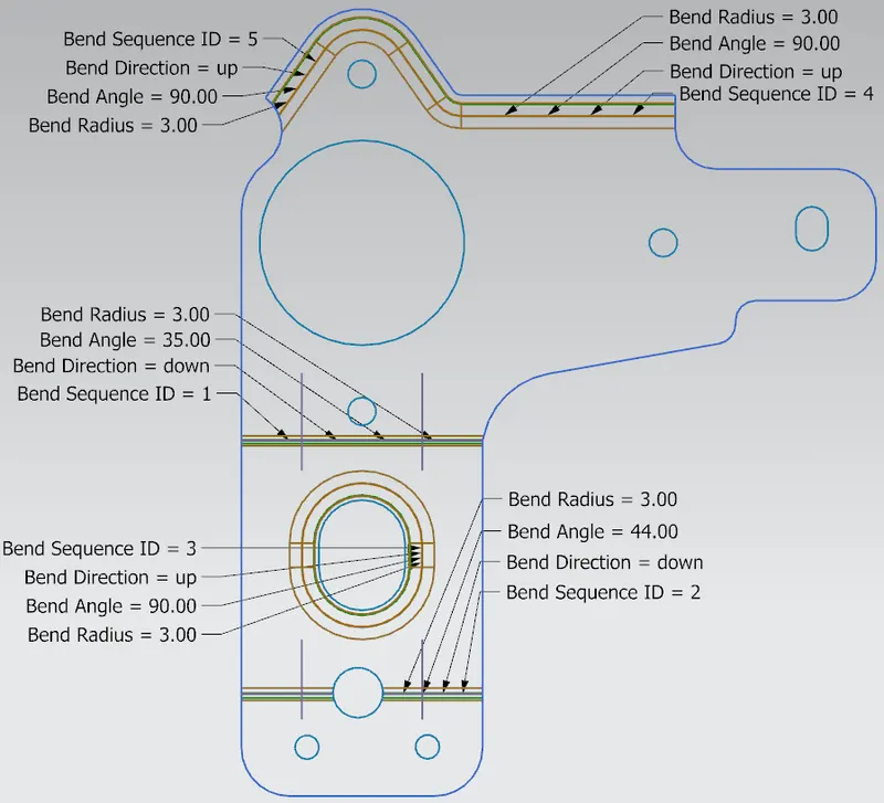
- Selecting Flat Pattern dialog box, clicking on the face and edge of the face to create flat pattern.
- Flatt Pattern can be viewed in the model views.
FLAT PATTERN View:
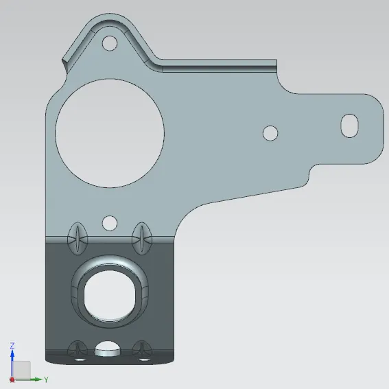
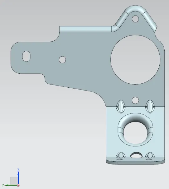
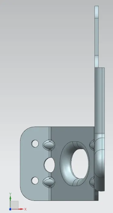
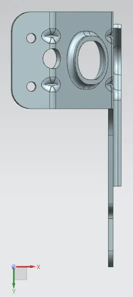
Screen shots of Model:
Front View:
Isometric View:
Right Side View:
Left Side View:
Top View:
Bottom View:
Detailed Drawing Sheet View:
Conclusion:
Finally, Sheet metal Bracket-II from 2D drawing has been created sucessfully using Siemens Nx application.