Advanced Sheet Metal Design Using NX Cad Challenge_2_Box Assembly
Sheet Metal Box Assembly
Objective:
The main objective is to design sheet metal box assembly using Siemens Nx application.
Introduction:
Here, we are going to study about how to create a solid model of sheet metal Box Assembly in siemens Nx Sheet metal Application. Using this application, how we are going to use tools step by step to complete the design. Then detailed explanation about tools used to make solid models and their features.
Design Methodology:
The steps involved in sheet metal box assembly are explained through flow charts.
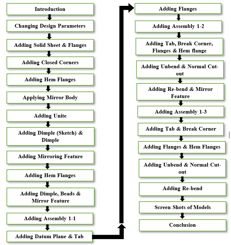
Description:
- Introduction:
- Start Nx 11 and create a new sheet metal model called Box Assembly.prt.
- Creating a sketch in XY plane and drawing a rectangle with an x-length of 200mm and a y-width of 150mm.
- Making coincide of y-width mid-point to origin.
- Exiting the sketch mode.
- Changing Design Parameters:
- Going to Menu - Preferences - Sheet Metal.
- In the Sheet metal Preferences dialog box, set all the four global parameters to 1 mm.
- Adding a Solid sheet and Flanges:
- Using the Tab button to create a first rectangular metal sheet of 1mm in thickness.
- Creating flanges to x-length on both sides up to 200 mm height, bend radius of 10 mm & angle of 90 degree. Length reference – Inside, Inset – Material inside.
- Again, adding flange on both sides with a length of 70 mm, bend radius of 10 mm & angle of 90 degree. Length reference – Inside, Inset – Material inside to the newly created flanges.
- Adding Closed Corners:
- Using the Closed Corner option, Type - close & relief, bends to close - Selecting adjacent bends, Corner Properties: Treatment - Closed, overlap - Closed, Gap - 0 mm.
- Select ok.
- Adding Flanges & Hem Flanges:
- Creating a flange of length 0.002 mm, bend radius of 0 mm on the end of 70 mm length flange.
- Applying length of 6.5 mm and bend radius of 0.5 mm to before created flange.
- Same above two steps were applying to another 70 mm length of flange. Applying ok.
- Applying Hem flanges to above created flange to combine sheet metal.
- In Hem flange dialog box, selecting Type - Open, inset - Material Outside, Bend radius - 5 mm & Flange Length - 5 mm and apply ok.
- Redoing the same steps for another flange to complete procedure.
- Exiting the sketch.
- Adding Mirror Body:
- Applying mirror body feature with respect to YZ plane to mirror body.
- Mirror body - Select Body to mirror - selecting YZ plane - apply ok.
- Adding Unite Feature:
- Adding Unite feature to combine two bodies as one body.
- Selecting Target body & Tool body to unite bodies.
- Adding Dimples (Sketch) & Dimple:
- Selecting Dimple button dialog box opens, Creating new sketch on the front plane.
- Creating Reference line as centred origin XYZ plane in the length of 100 mm & selecting centred rectangular button to draw a sketch of length of 360 mm & width of 30 mm with respect to end point of reference line.
- Selecting Move curve button to change the angle of rectangle box to 20 degree. To change angle, select all lines, drag & place centre point to the reference line end point. Apply 20 degree to change angle.
- Redoing same steps to create another sketch with respect to the angle of 340 degree.
- Select fillet button, set radius 10 mm & select all corner points to be filleted.
- Exiting the sketch.
- Select lines & set depth of 2 mm, material outside option to apply dimple feature and select ok to validate.
- Adding Mirror Feature:
- In mirror feature dialog box, select all drawn lines with respect to XZ plane to mirror feature.
- Exiting the mirror feature.
- Adding Dimple, Beads & Mirror Feature:
- Selecting bottom of YX plane, draw a centre pointed rectangular box origin of (0,0) with the length of 330 mm and width of 30 mm.
- Filleting corners with respect to radius of 10 mm.
- Exiting the sketch to apply dimple feature.
- Selecting all lines and setting depth of 2 mm, material outside option to create dimple.
- Selecting Bead button, create circle on the same plane at the corners to the following dimensions of 15 mm length & 15 mm width and exit the sketch to create bead with respect to circular cross section, depth of 2 mm & radius of 2 mm.
- Select ok to validate.
- Mirroring this bead feature to all corners with respect to YZ & XZ planes.
- Selecting closed hem flange (with respect to flange length of 2 mm, material outside option) to the top plane of box wherever necessary to strengthen the edges & smooth surface.
- Adding Assembly 1-1:
- Selecting Assemblies tab, select create new button to open new sheet metal.
- By Clicking on Assembly navigator, we see newly created Assembly 1-1 sheet, Right click on that sheet to make as work part. Then click Wave geometry linker to sketch on the part.
- Adding Datum plane & Tab:
- Clicking on Datum plane button create new plane with respect to XY Pane to sketch at a distance of 203 mm.
- Click ok to validate and draw a centre point rectangle from origin (0,0) with the length of 402 mm & width of 152 mm.
- Creating a circle of diameter 22 mm with respect to outer tangent curve of an existing body. Create vertical & horizontal lines form mid of circle to cut the circle into 1/4th. Then click on quick trim button to trim a circle & extra lines to make an arc.
- Redoing the above steps to make arc at remaining three corners.
- Exiting the sketch and click on tab button to make sheet of 1 mm thickness downwards to touch with box.
- Adding Flanges:
- Creating flanges on each edge with the length of 3 mm, length reference àweb, insetàmaterial outside & bend radius of 0.5 mm. Click ok to validate.
- Adding Assembly 1-2:
- Selecting Assemblies tab, select create new button to open new sheet metal.
- By Clicking on Assembly navigator, we see newly created Assembly 1-2 sheet, Right click on that sheet to make as work part. Then click Wave geometry linker to sketch on the part.
- Adding Tab, Break Corner, Flanges & Hem flange:
- Creating sketch on right side of part and draw a rectangle of length 55 mm & width 20 mm with respect to the origin and align sketch at a distance of 17 mm from top, then 3 mm wide from origin.
- Exiting the sketch and selecting tab button to create sheet of 1 mm thickness.
- Selecting break corner button, click left side bottom edge to bend radius 10 mm and click ok to validate.
- Selecting flange button, clicking on the top edge of the newly created tab to add flange of length 4 mm, angle - 40-degree, length reference - web, inset - material outside, bend radius - 5 mm and click ok to validate.
- Following the above steps as same but length of flange updating to 3 mm.
- Creating hem flange, select open loop type, inset - bend outside, bend radius - 5 mm and Sweep angle - 325 degree. Then click ok to validate.
- Adding Unbend & Normal Cut-out:
- Selecting Unbend feature to unbend flange & hem flange by clicking face flange & bend flanges. Then click ok to validate.
- Selecting normal cut-out button, click on create sketch to draw rectangular box length of 38.2 mm & width of 14 mm.
- Creating another rectangular box follows the above steps. Gap between two boxes is 14 mm. Exiting the sketch to apply normal cut-out with respect to the depth of 5 mm. Then click ok to validate.
- Adding Re-bend & Mirror Feature:
- Selecting re-bend button, click on bends to originate its before formation. Then click ok to validate.
- Selecting mirror feature, select bodies with respect to XZ plane as a reference plane to mirror feature. Then click ok to validate.
- Adding Assembly 1-3:
- Selecting Assemblies tab, select create new button to open new sheet metal.
- By Clicking on Assembly navigator, we see newly created Assembly 1-3 sheet, Right click on that sheet to make as work part. Then click Wave geometry linker to sketch on the part.
- Adding Tab, Break Corner:
- Selecting tab button, create sketch to draw a rectangle of length 128 mm & width of 20 mm with respect to top XY plane on the edge of sheet.
- Exiting the sketch to create tab with thickness of 1 mm.
- Select break corner button, click on top corner edges to bend radius of 10 mm and click ok to validate.
- Adding Flange & Hem Flange:
- Selecting flange button, to create flange on the edge of newly created tab with length of 13 mm, at an angle of 40-degree, length reference - web, inset - material outside, bend radius of 0.5 mm. Then click ok to validate.
- Creating hem flange, select open loop type, inset - bend outside, bend radius - 5 mm and Sweep angle - 325 degree. Then click ok to validate.
- Adding Unbend & Normal Cut-out:
- Selecting Unbend feature to unbend flange & hem flange by clicking face flange & bend flanges. Then click ok to validate.
- Selecting normal cut-out button, click on create sketch to draw four rectangular boxes length of 48.3 mm, width of 13.5 mm, gap of 16 mm from start and 14 mm as follows till end.
- Exiting the sketch to create cut-out.
- Adding Re-bend:
- Selecting re-bend button, click on face & bends to originate its before formation. Then click ok to validate.
- Redoing the above steps to complete the re-bend part, then click ok to validate.
Screen Shots:
Isometric View:
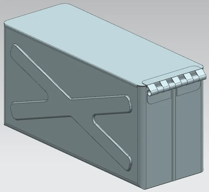
Front View:
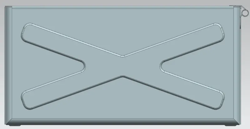
Top View:
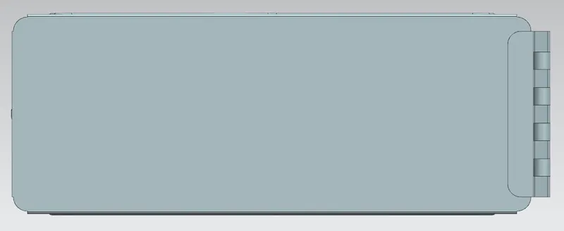
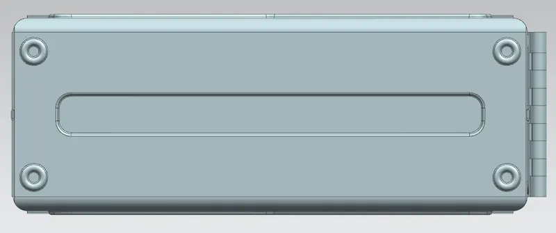
Bottom View:
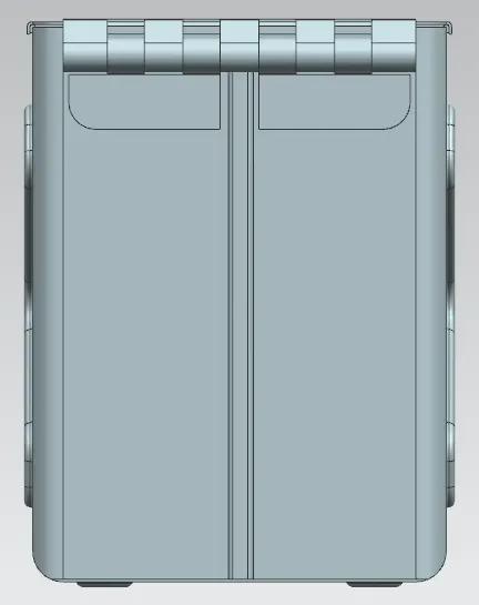
Right Side View:
Conclusion:
Finally, sheet metal Box assembly has been created successfully using siemens Nx application.