Week 8 - Challenge 5 - Core & Cavity Design
AIM : Design of CORE & CAVITY OF SWITCH PANEL BEZEL
SOFTWARE USED : CATIA v5
Drafting analysis : The Draft Analysis command enables you to detect if the part you drafted will be easily removed. This type of analysis is performed based on color ranges identifying zones on the analyzed element where the deviation from the draft direction at any point, corresponds to specified values.
PARTING SURFACE :
Generally,injection mold has two major components : the movable halve and the fixed halve , during the injecction molding process, these two halves are pressed tightly from a sealed hollow to avoid the melt flow leakage and maintain certain holding pressure, the pressed surface are called parting surface , usually parting surface are the biggest projection outline of the part.
Parting surface design principles
Parting bsurface design directly affects the product quality , ease of construction and opearation of the injection mold , the mold design is one of the key facctors to success.
DESIGN PARTING SURFACE SHOULD FOLLOW THE FOLLOWING PRINCIPLES :
- Design the injection mold simple as possible .Avoid or reduce side parting as much as possible to reduce complexity of the mold making.
- Ease of de-molding as far as possible, for instance the plastic parts should stay in fixed halve of injection mold and should ejected by ejection system avoid , side de-molding action,
- Ensure the dimension accuracy of the molded parts ,Try to make the parts similar dimension accuarcy reqirements in same mold to reduce manufacturing and assembly errors .
- Ensure apperance reqirement of molded parts,finish or mismatch usually occurs on parting surface , so the parting surface should not be designed on high quality requiremnent surfaces.
- Ensure adequate venting.If possible parting surface should be place at the end of the mold flow.This is going to be advantage of fillng and venting.
Design of core in step by step explanation in image portration .
Step 1 : To etrapolate class A surface for 17 mm
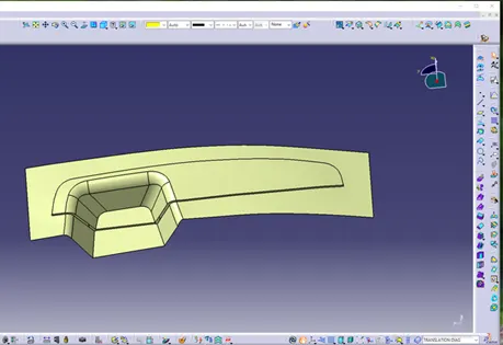
Step 2 : trim class A with class c to get inside portion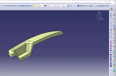
Step 3 : Now, trim the B surface with with output of Class A & C that will be parting surface with resprect to area
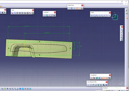
Extrude the skectch overall throgh the tooling direction are trim it with parting surface.
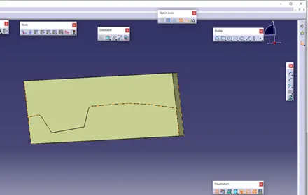
Final output of core design
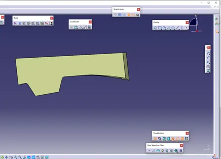
Closed part body of the core design
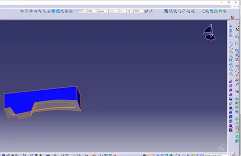
Similarlly,Repeating the same as done for the cavity part and trim it on other side surface
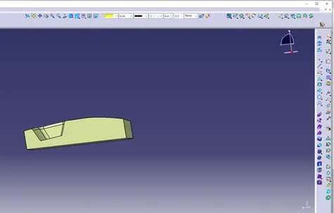
FINAL Close body surfaces of Core & cavity are,
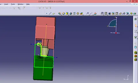
Intersection of parting body represented
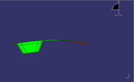
Draft Analysis
When developing parts for plastic injection molding, applying a draft (or a taper) to the faces of the part is critical to improving the moldability of your part. Without it, parts run the risk of poor cosmetic finishes and may bend, break, or warp due to molding stresses caused by the plastic cooling. Equally important, an absence of a draft may prevent parts from ejecting from the mold, damaging not only the parts but possibly the mold itself—a costly and time-consuming detour.
In CATIA the draft analysis can be found by Insert > Analysis> Feature Draft Analysis.
Generally, the nominal draft angle will be 3 degrees.
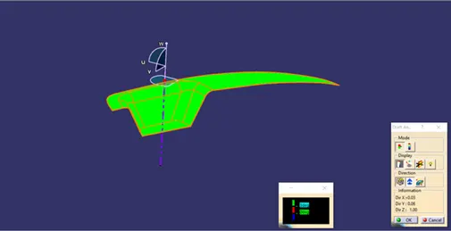
In the above image, the tooling direction is fixed by placing the compass on the tooling axis of the component. Once the tooling direction is locked, the component is selected and draft analysis is done.
- The value of the minimum draft angle is changed to 3 degrees.
- The above image with all the faces in green color shows that all the faces have a minimum draft angle for the tooling. Hence, the design of the component can be finalized.
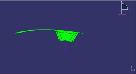
FRONT VIEW
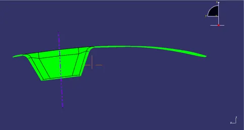
BACK VIEW
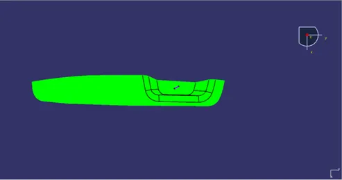
TOP VIEW
DRAFT ANALYSIS OF THE SOLID PART
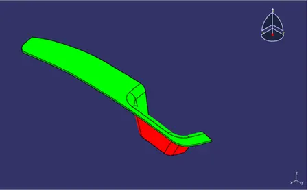
ISOMETRIC VIEW
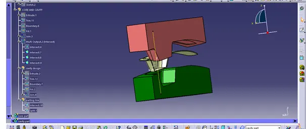
Tree structure:

conclusion:therefore Creation of the Core and cavity blocks for the switch bezel design has been done.