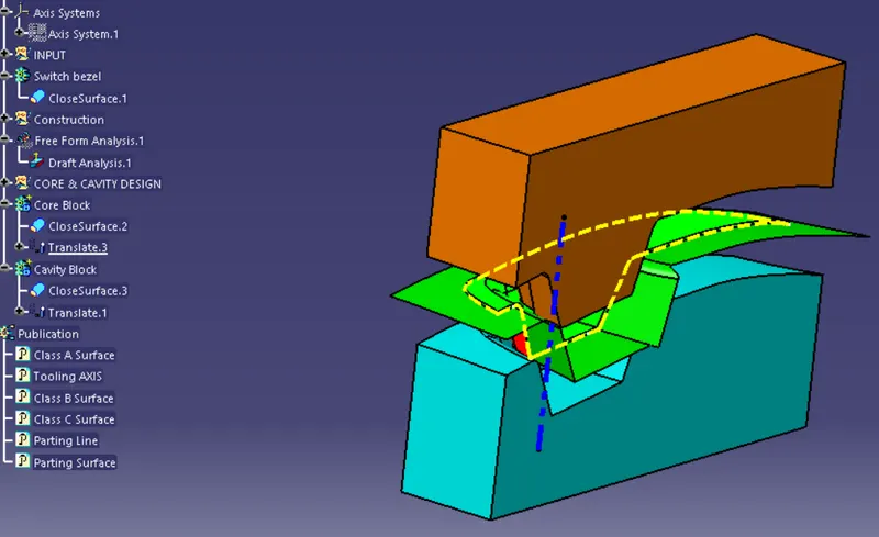
Week 8 - Challenge 5 - Core & Cavity Design
Class A Surface Creation:
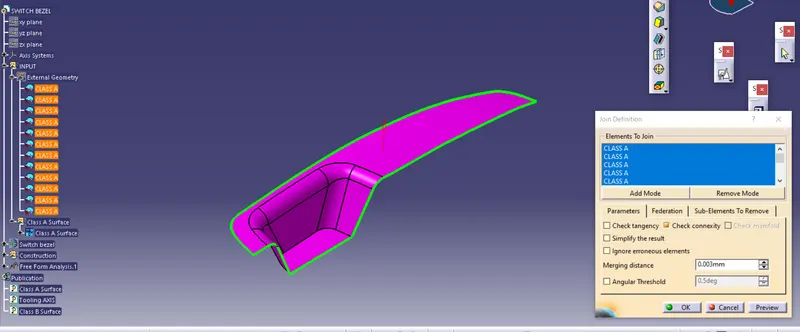
After receiving A surface as input we have to make sure all srufaces are connecting and if surfaces are not connected or properly merged then we have to use JOIN command to make proper Class A surface without any deviations and gaps between the surfaces
In this assignment input Class A surface was not properly merged and have gaps in between to I have to apply some operations to make thes surfaces connecting
Tooling Axis Creation:
1. We analyse the best possible tooling direction using the X/Y/Z planes we create line for reference.
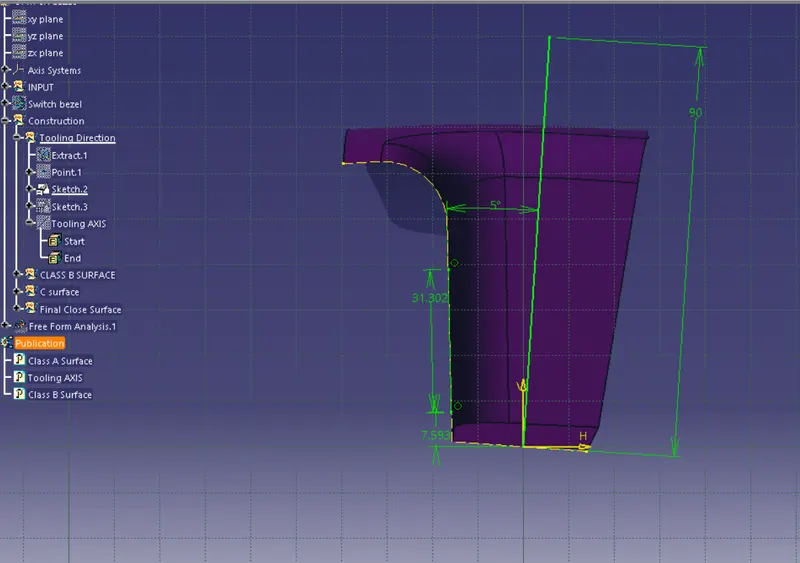
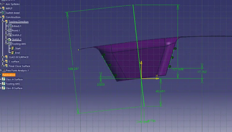
Creation of Tooling Direction using Bisecting line:
CLASS B Surface Creation: Now we make class B surface using the plane surfaces of Class A.
1. First we use extract command to copy the plane surfaces of Class A and then Untrim those surfaces.
2. Then we get the basic surfaces and extrapolate then so that they are easy to Trim later.
3. After extrapolating the surfaces we trim then together to form sharp model.
4. We take offset of the surfaces as per the required thickness of the bracket.
5. After offset we trim all base surfaces and walls together and form a single sharp model.
6. After trim we apply Edge fillet to sharp edges.
Now B surface is formed and we can publish the final B surface.
Class C surface Creation:
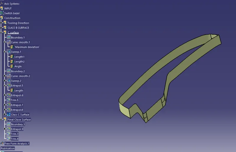
1. We take boundary of class A surface and sweep it using draft direction and give 3 deegre draft in direction which should be cleared as per tooling direction.
Close surface:
After creating the Class A B & C surfaces we make close colume using trim
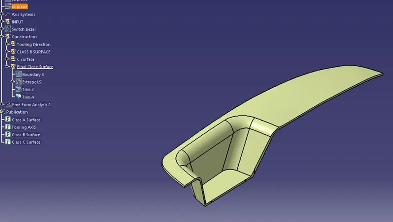
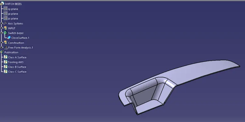
Now we make it solid body using Close surface command in part body workbench
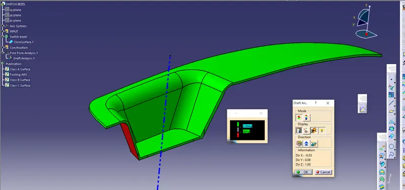
DRAFT ANALYSIS:
CORE & CAVITY DESIGN
Parting surface& Partilng Line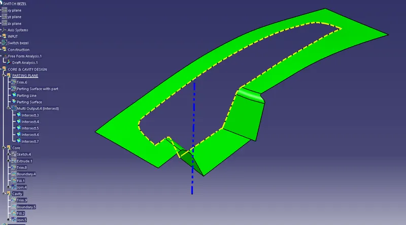
Core
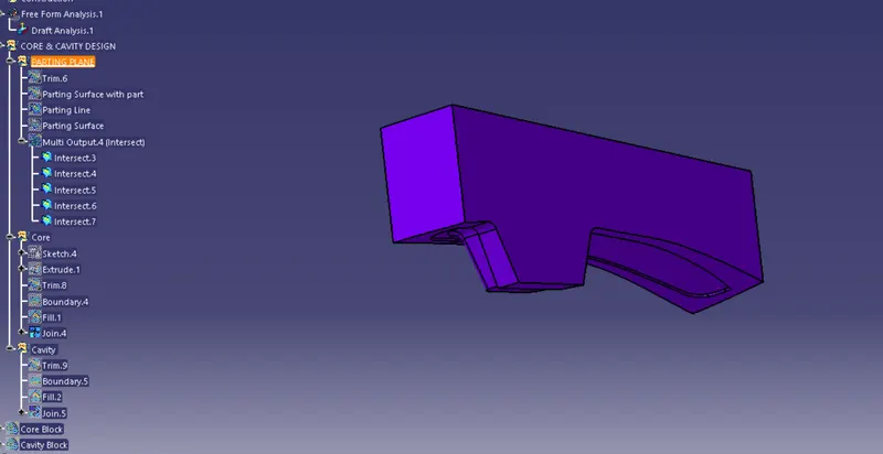
Cavity
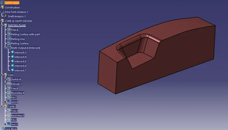
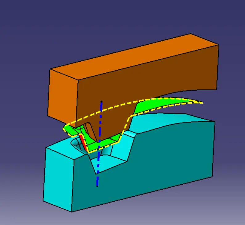
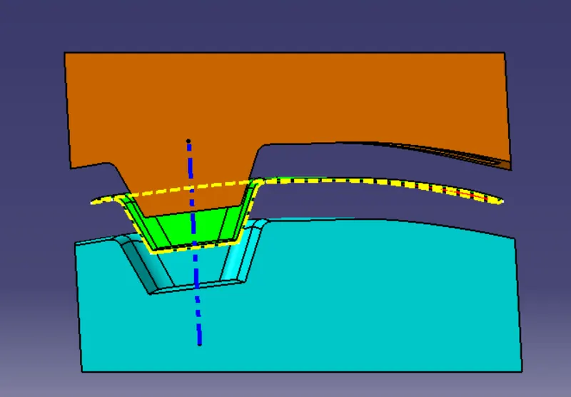
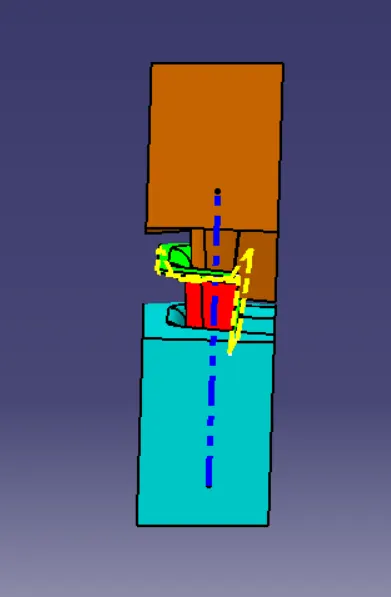
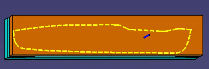
Core and Cavity
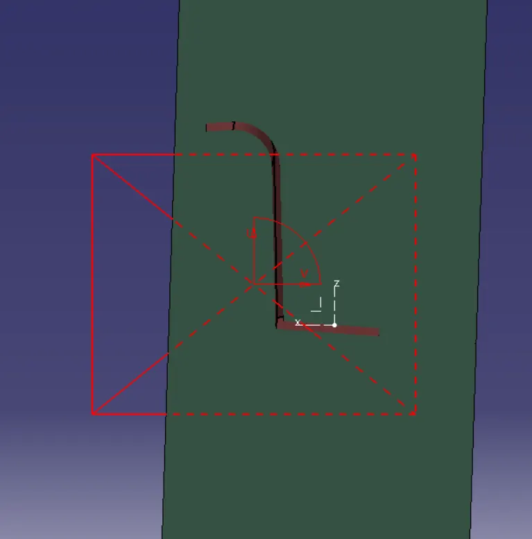
ISO View:
FRONT VIEW:
SIDE VIEW:
TOP VIEW:
Publications: