Challenge 7 : Concept Modelling of Steering Wheel
Topic: Concept Modelling of Steering Wheel
Objective: To create the surface model of steerng wheel using Autodesk Alias Design.
Introduction: In this assignment we create surface model of Steering Wheel by following a proper approach.With the help of images we visualze the surface flow and create primary surfaces first then we create transition surfaces. After creating these surfaces we focus on merging of surfaces in critical areas. Areas where we hold the steering wheel while using the buttons n steering wheel. So those areas should be smooth and easily accessible.
Please refer below for the Flow Chart:
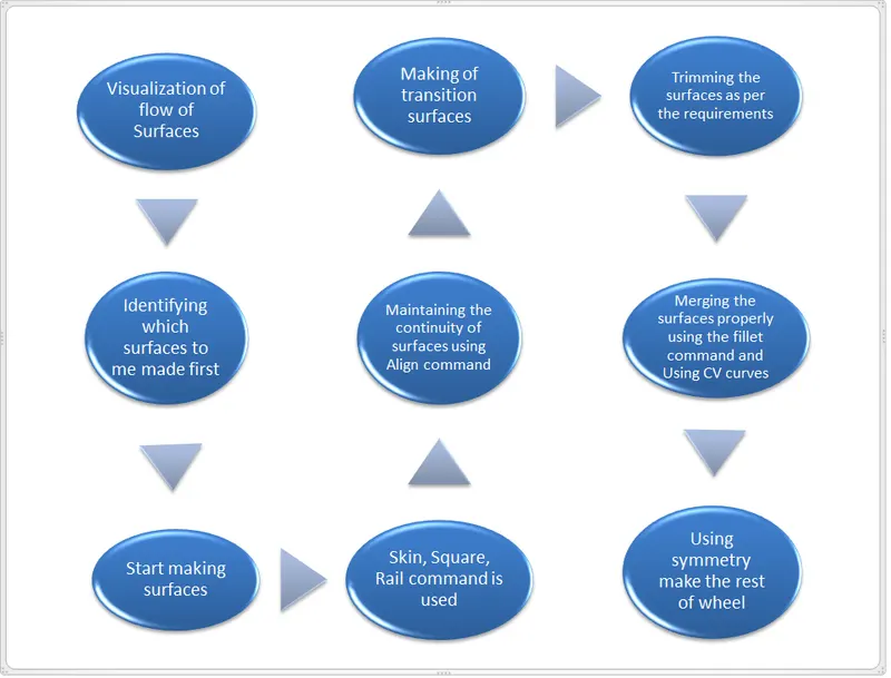
Description: Step 1: Import the canvas image of Side view of Steering Wheel
Step 2:Visualise the surfaces using the picture given identify the primary surfaces to be build first.
Step 3: Build the surfaces using Rail, Square, Skin command.
Step 4: Surfaces made in patches should follow the G2 continuity so that they look smooth and continous,Align using G2 continuity.
Step 5: Start making transition surfaces using the Rail, Square, Skin command.
Step 6: Surfaces which are to be trimmed should have G0 continuity so that surface fillet can be applied.
Step 7: Apply Surface Fillet for smooth transition between diffrent surfaces and removing sharp edges from model.
Step 8: After fillets use CV curves continuos to fillets for mering of critical areas.
Features Used :
CV Curve: It is made by joining of CV( Control Vertices). The first CV is marked as box then next as ‘U’ Shaped and then all others marked as ‘X’. CVs decide the shape of the curve.Degree and Span of CV curve: It decides the continuity of curve. If we have a long continuous curve then we should use single span curve and increasing the degree to make the curve smooth and continuous.
Blend: It is used to join two curves. They can be formed in curvature continuity and also with the help of editor we can change its continuity to tangency.
Trim: Trim a surface by removing (actually hiding) any part of the surface bounded by curves-on-surface or cross sections.You can also split (divide) a surface into multiple surfaces.
Project: It used to project the curves on surfaces to perform the trim operation there must be curve projected on the surface
Skin/Sqaure/Rail: These are used for generating the surfaces.
Surface Blend: This generate blend surface between the two selected curves.It is used where smooth merging of the surfaces are required.
MS Draft: It generates the surface from the slected edge of surface at some draft angle and also length can be modified accordingly. It is useful where the surfaces are at some angle to each other and intersecting to common edge.
Instersect: It generate the intersection curve between the two selected surfaces. It helps us to trim the surfaces and later apply surface fillet.
Surface Fillet: It is used to give the round curvate to sharp edges it make the transition between surfaces smooth.
Dettach: It is used to divide surface using its own edge or boundary.It also separates surface along with CV hull.
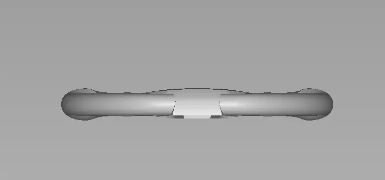
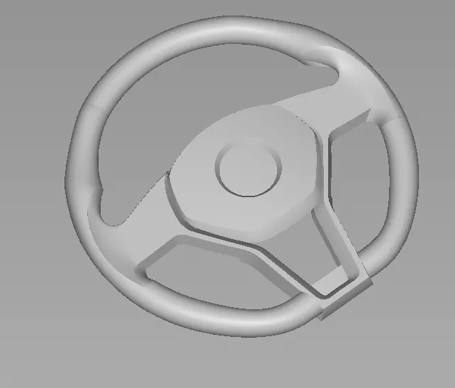
Refer following pictures of model
Front View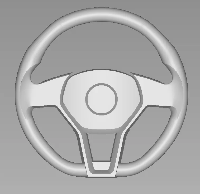
Side View
ISO View
Conclusion: In this assignment we made the Surface Model of Steering Wheel .First we visualize the image then identify the surfaces which are to be build first. Primary surfaces are made with smooth G2 continuity then transition surfaces are made.
We merge the surfaces using the blend where more than two surfaces combine to from a single smooth surface.Where the surfaces are not clear from the reference picture then we have to interpret the surface and build surfaces accordingly.So by following this approach we complete the surface model of steering wheel of Mercedes Benz Car.