Week 8 - Challenge 5 - Core & Cavity Design
Week 8 - Challenge 5 - Core & Cavity Design
Aim:
- To perform draft analysis on the switch bezel component
- To create Core and Cavity Blocks for the switch bezel
- To write a detailed report based on the Draft analysis result
Given Input:
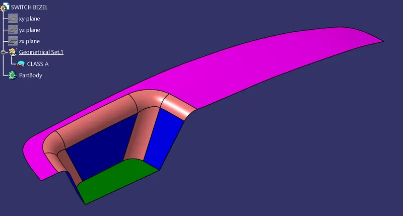
Draft analysis
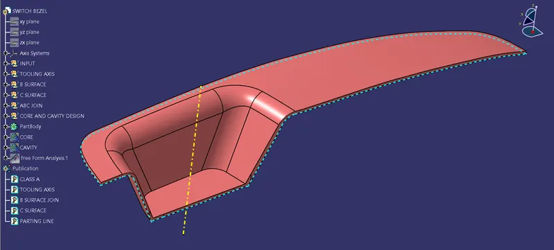
Tooling axis and Close body is created from the given class A surface for the Switch Bezel in the previous exercise.
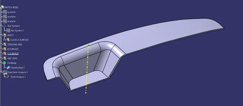
Draft Analysis:
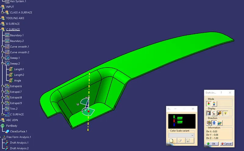
- Draft analysis tool can be brought up from Insert > Analysis > Feature Draft Analysis
- The compass is dragged and dropped on to the tooling axis.
- The required angle of draft to be checked can be enetered in the color scale.
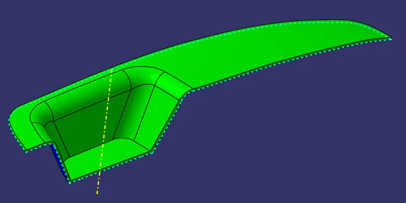
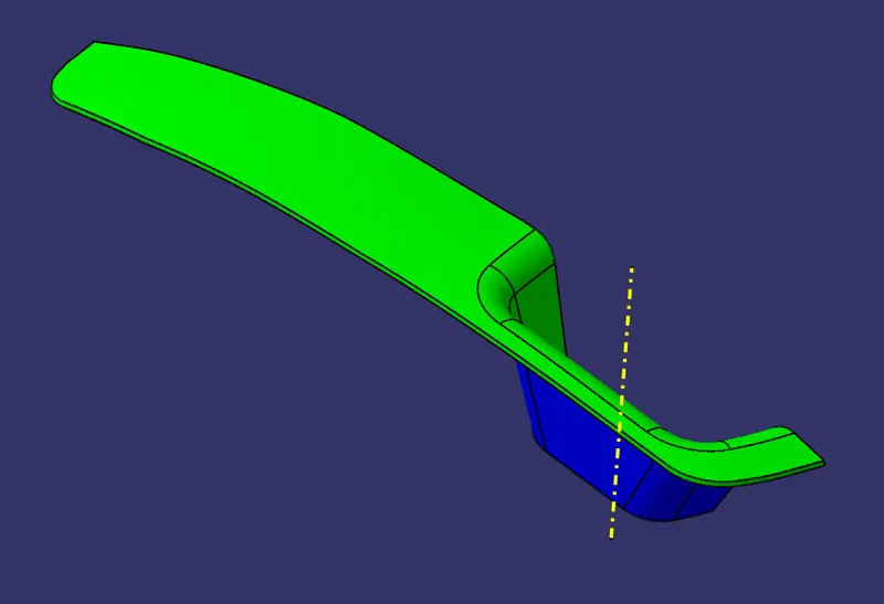
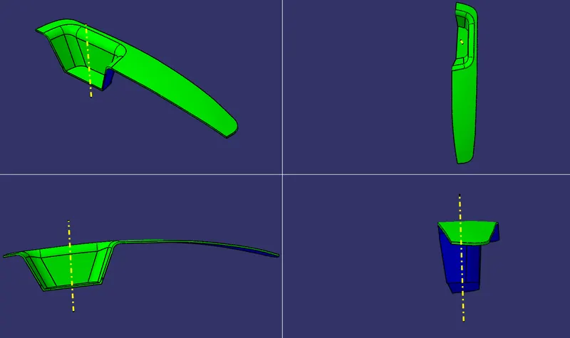
- Draft analysis on the final body shows that the Class A surface (Green) will be formed by the Cavity while the B and C surface (Blue) will be formed by the core.
Creation of parting surface
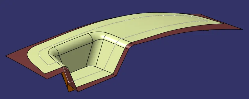
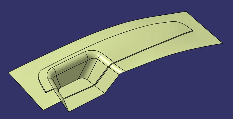
The boundary of the Class A surface is created and using that boundary the class A surface is extrapolated.
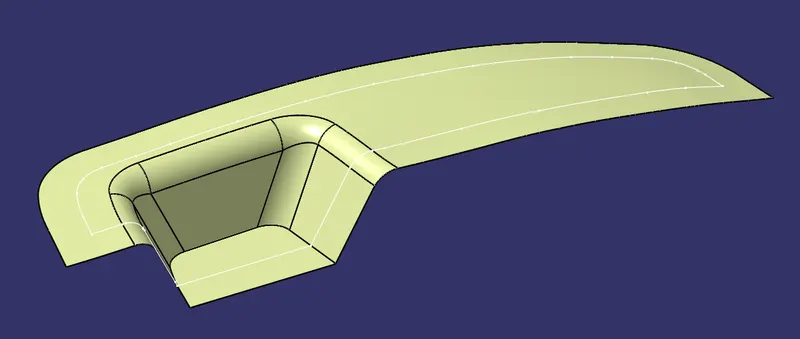
This extrapolated surface is trimmed with the C and B Surface as shown below.
Creation of core and cavity
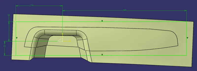
A sketch is created on the XY Plane and a rectangle is created enclosing the profile of the Switch Bezel.
This rectangle is swept along the tooling direction
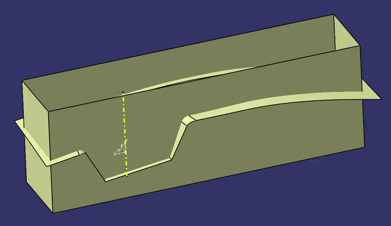
This swept surface is trimmed with the parting surface to give the core surface.
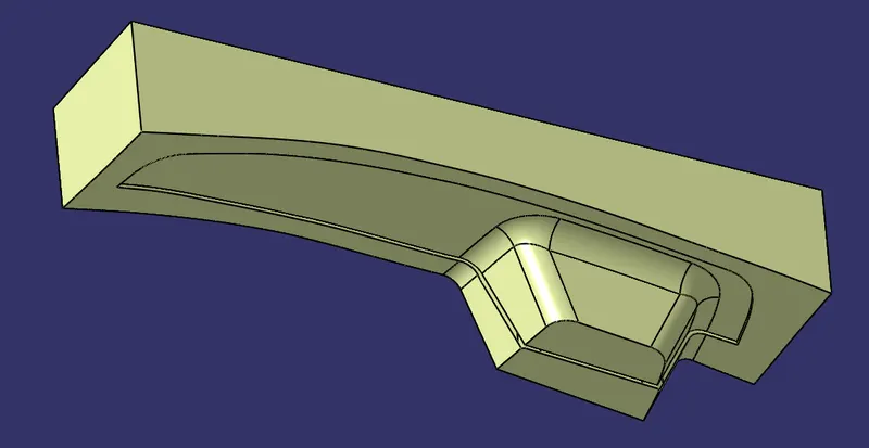
Similarly the B Surface is trimmed with the swept surface to give the cavity surface
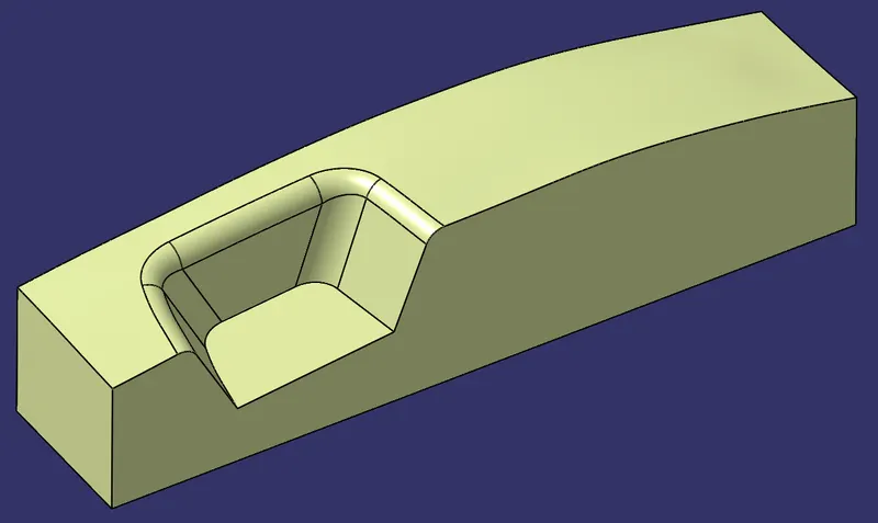
These surfaces are made into a solid by Close Surface command
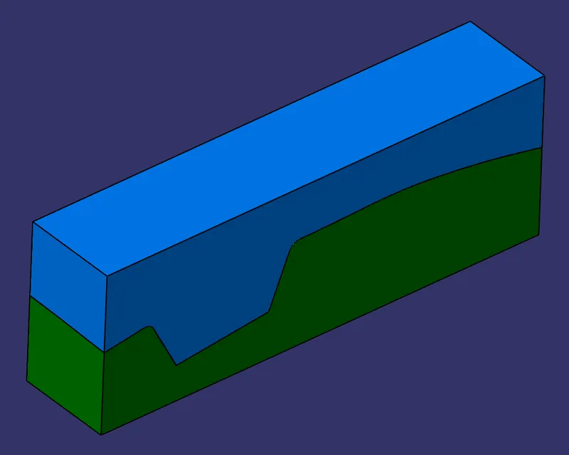
These intersects show the profiles of the Core, Cavity, Part and the Parting Surface.
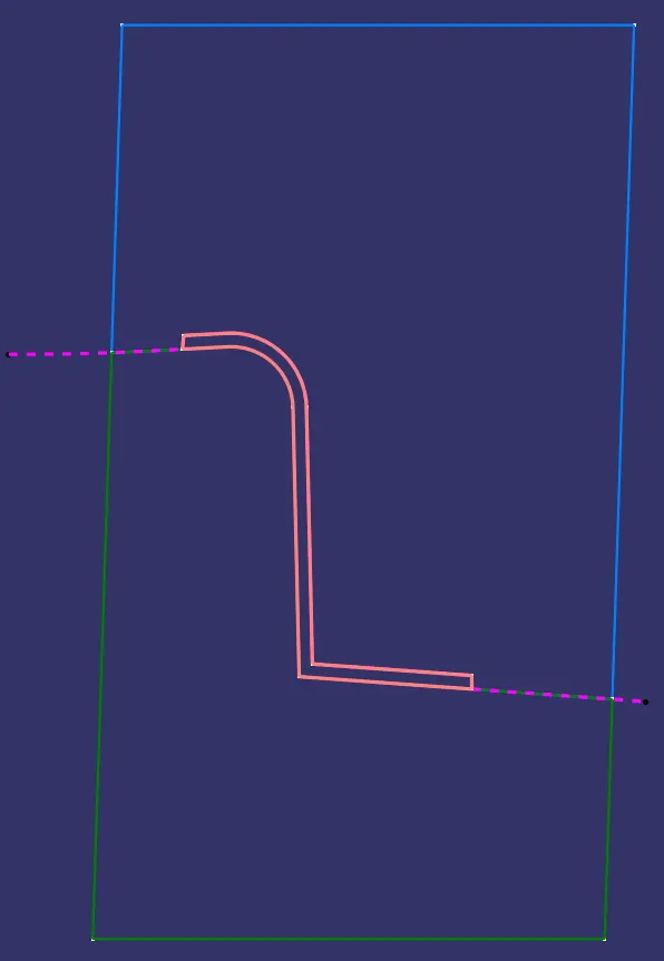
Intersect of the C Surface and B Surface gives the parting line