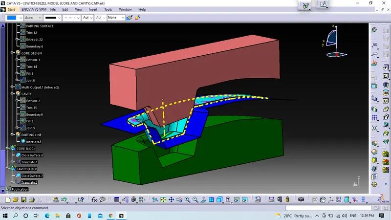
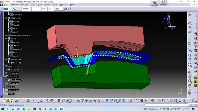
Week 8 - Challenge 5 - Core & Cavity Design
Objective:- We will create Core and Cavity block for the switch bezel model.
1. Steps for tooling axis creation
- First step we will extract the base surface from Class-A surface then we will take on the surface after the we insert the axis system on this point. Now we will go into the sketcher workbench where we will select the position sketch. In position sketch we will select the reference plane like if we will take( YZ plane then we will get tooling direction along Y-axis and ZX plane then we will get tooling along x-axis).
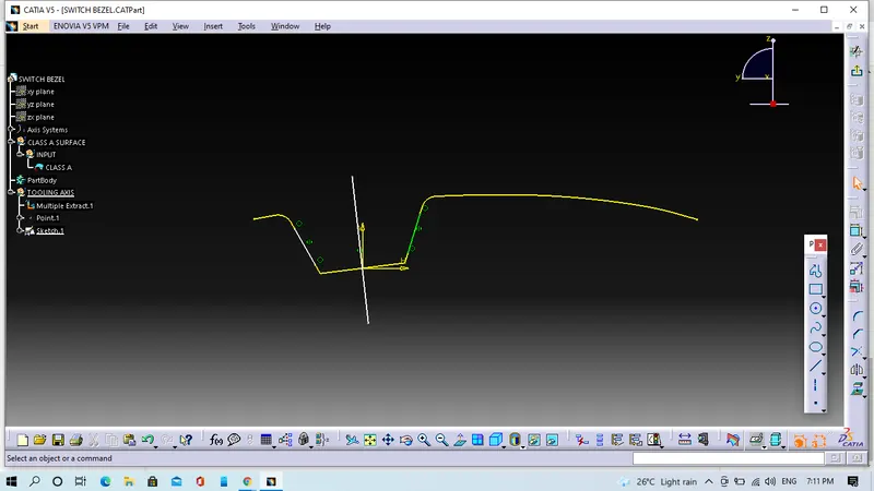
- Second steps we will take intersection of a class A with XZ plane then we will draw a line on intersection line Class A. Since we do not have any another surface to draw a line and this will passing through point with 3 degree angle with reference plane.
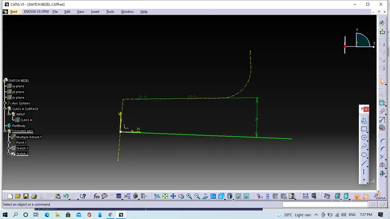
- Third step we will use bisecting method to get actual tooling axis.
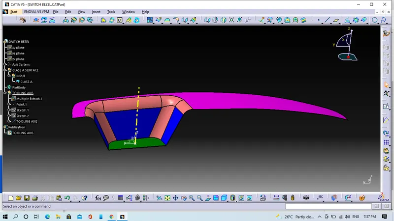
2. Now we will perform on draft analysis
- In draft analysis we have to follow some steps, click on the compass icon, drag it to the tooling axis and align it with the tooling axis. After that we have to click in option of customize view parameter mode and select the material option and then we will click on the surface.
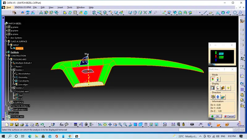
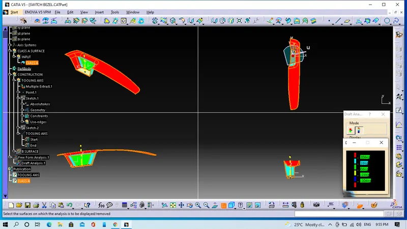
In the above image we can see that the surface is green colour has draft angle greater than 2 degree and which is most required for tooling feasibility.
- Now we will check the degree of the surface for that we will go to the features draft analysis toolbar and click the analysis under the running point option after we will move the mouse cursor on the surface it gonna shows hoe much drgree is their for that specific point. So if the degree is ok as required in model then it will be ready for design.
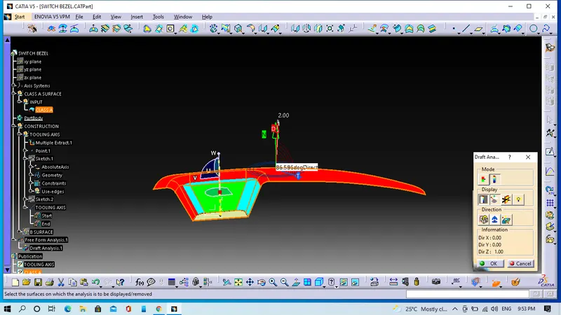
- This image is showing full draft analysis.
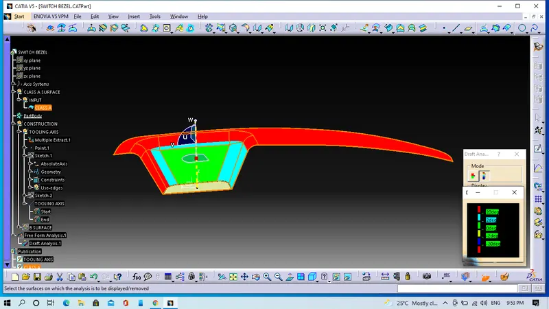
- Screenshots of the draft analysis in various orientation (Isometric, Front, Side and Top View).
3. Core and Cavity design
- We will extrapolate the Class A surface as well as B and C surface.
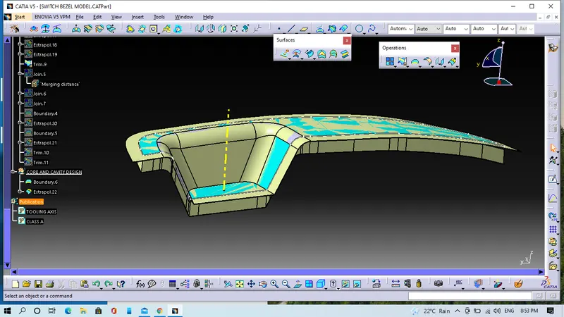
- We will trim the Class C surafce with B surface.
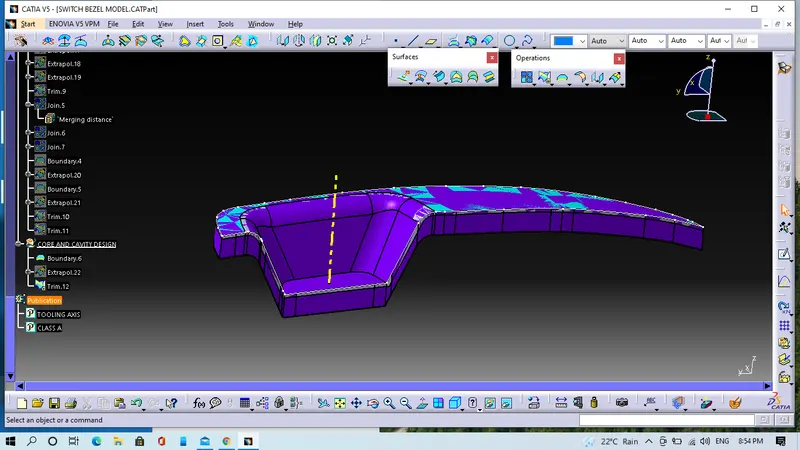
- Now we will trim the extrapolute Class A surface with extrapolute Class C surface.
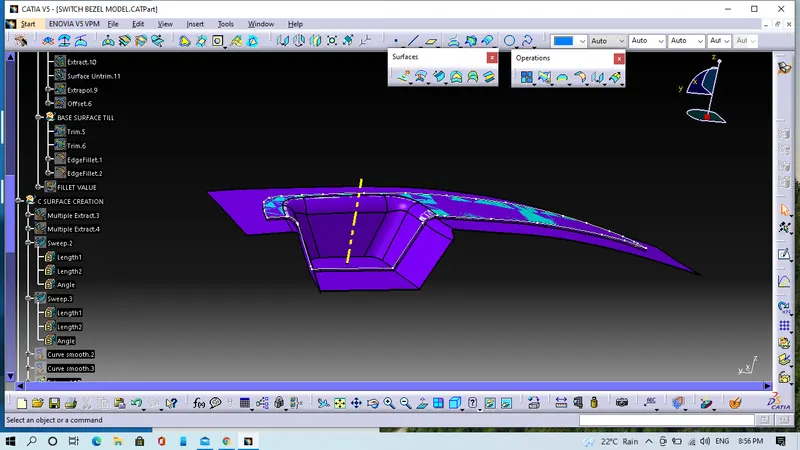
- We will select XY-Plane, select positioned sketch. Draw a rectangular box which should be include whole surface.
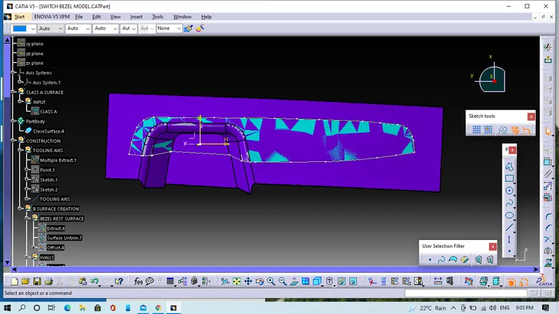
- We will extrude the rectangular box along the tooling axis and we will trim the outer edges.
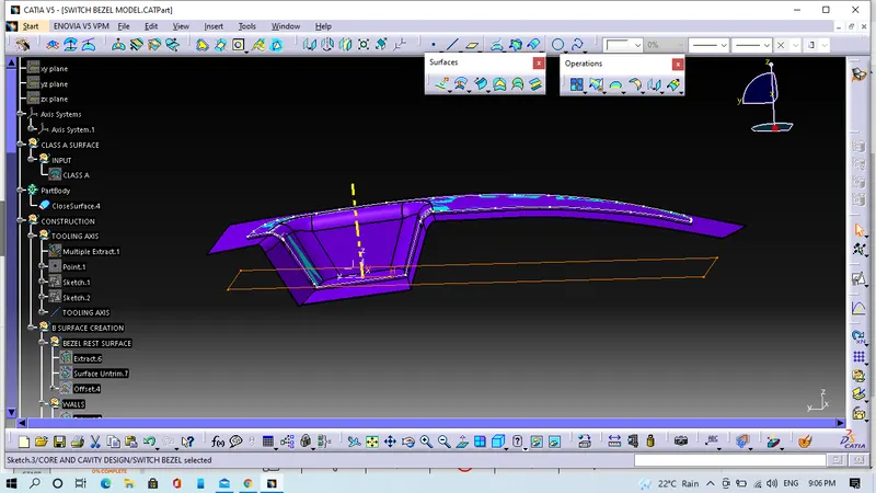
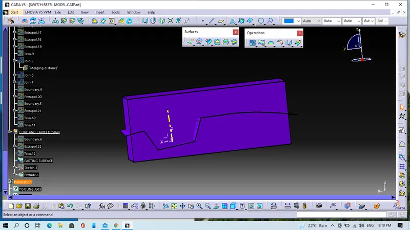
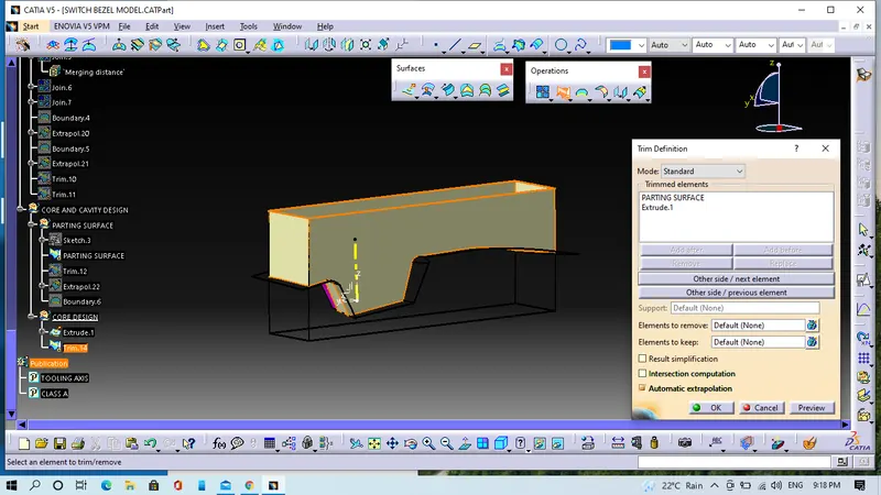
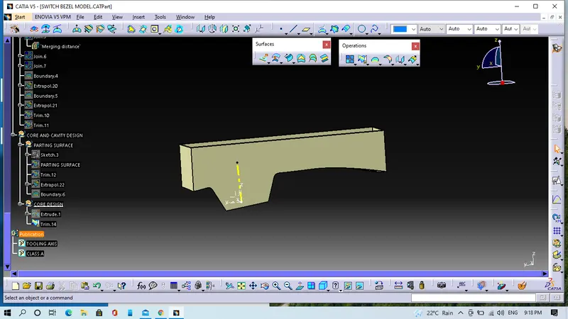
- Now we will use fill command for fill the Top surface.
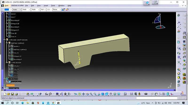
- We will make solid body and this will be the CORE.
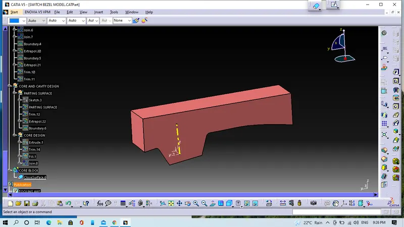
Now we will similarly devlop Cavity block by the help B-Surface.
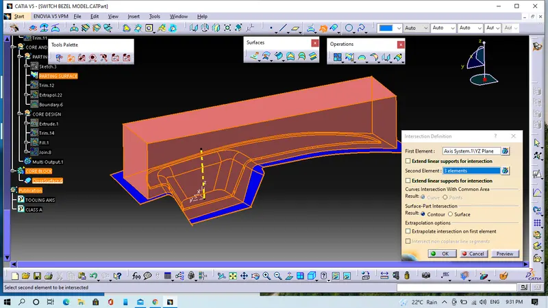
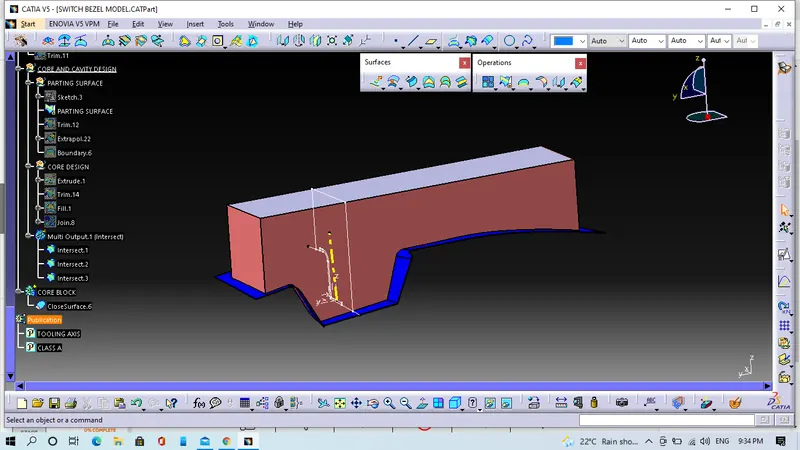
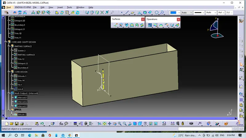
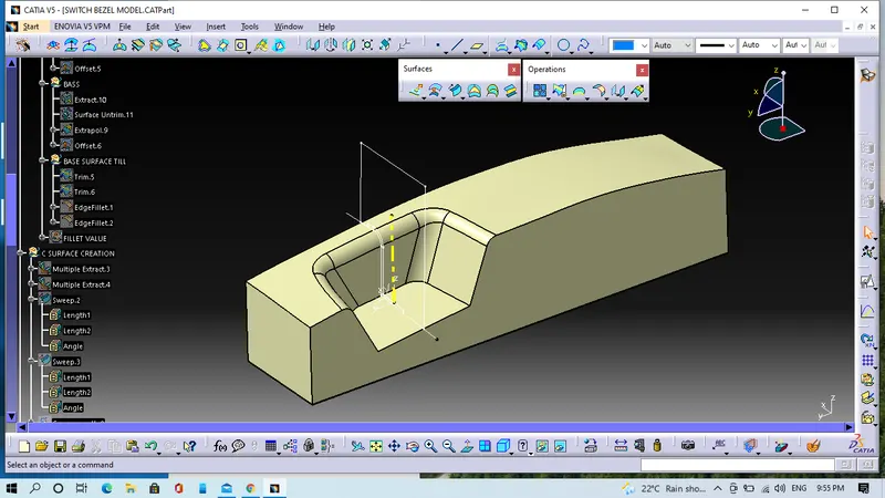
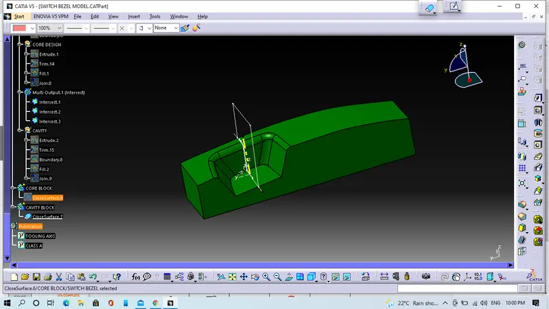
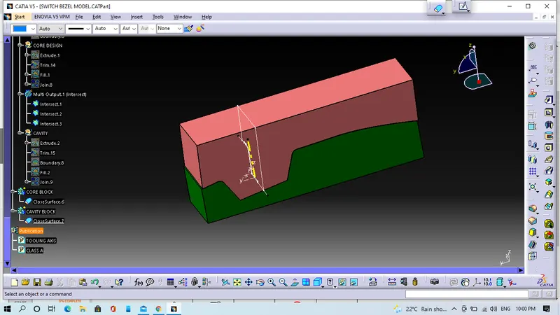
We will create parting line and parting surface
To create parting line on this model, we have to folloe some steps
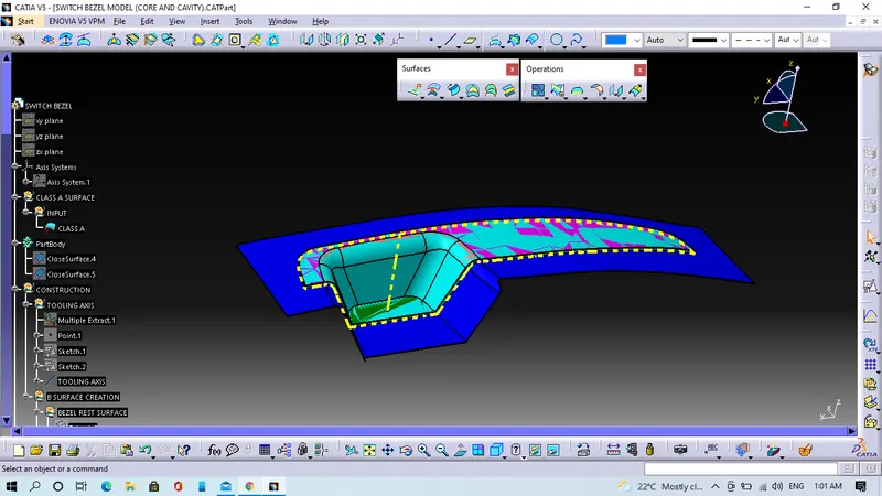
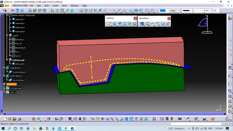
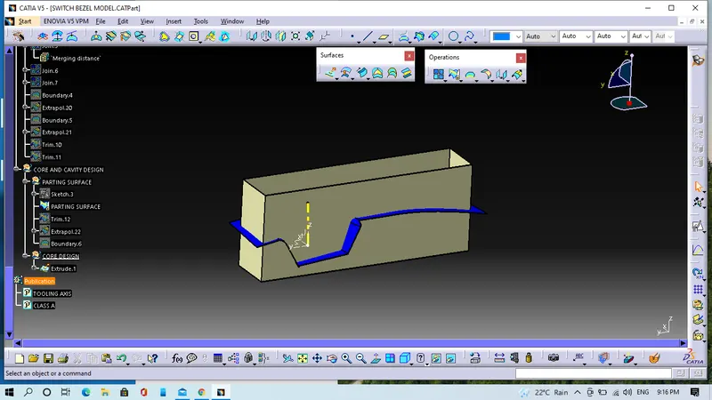
In this below image Blue colour surface is showing Parting surface and Yellow colour line is showing Parting line.