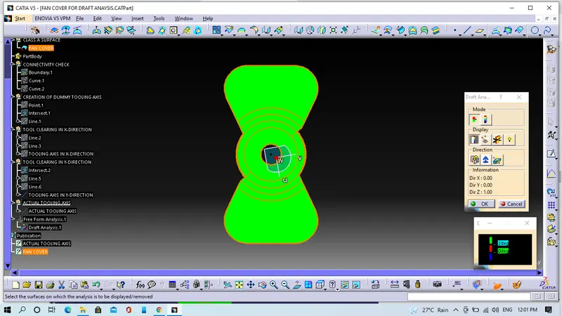
Week 8 - Challenge 1 - Draft Analysis on a Fan Cover
Objective:- To perform the draft analysis of given Class-A surface
Basic introduction about Draft, Draft angle and Draft analysis
Draft:-Draft is the amount of taper for moulded or cast parts perpendicular to the partling line.
Draft angle:-Draft angle is a taper applied to the vertical to assist with releasing the part from the mould.
Draft analysis:-The Draft analysis command enables you to detect if the part you drafted will be easily removed. This type of analysis is performed based on colour ranges identifying zones on the analyzed element where the deviation from the draft direction at any point, corresponds to specified values.
For the Plastic component, the 3 degree draft is nominal ,for the supporting element the minimum draft value is 0.5 and for the texture surface upto 7 degree draft is nominal.
Steps for Tooling axis creation
1. First we have to check the connectivity of the class A surface. After that we will check on join command and see how it will connected just ensure that no surface gap between the surfaces and by the extracting of given class A surface we can visually check the connectivity of the model.
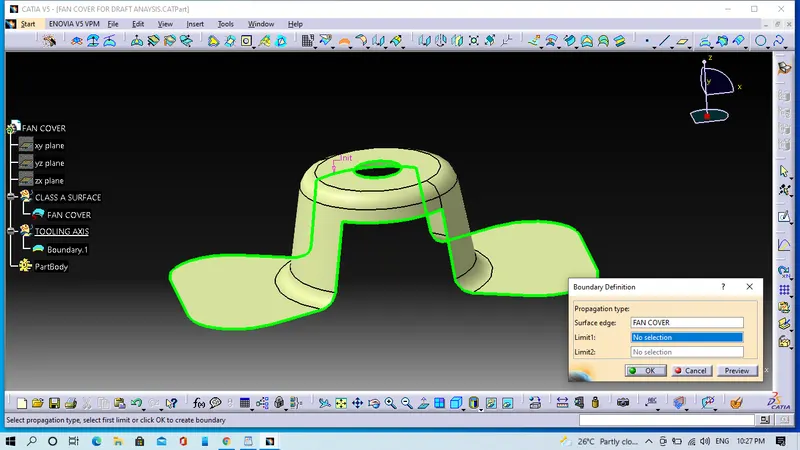
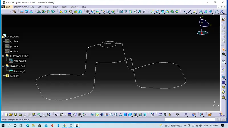
2. Create an axis system at the center of the top hole
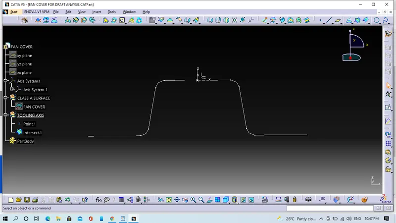
3. Creation of dummy tooling axis.
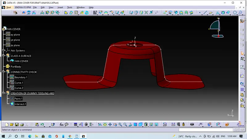
4. Tool creation in x-direction: Insert the axis system, take the intersection of plane and the surface. Now find the lines lying approximately parrel to dummy tooling axis.These are the lines which draft angle will be provided.
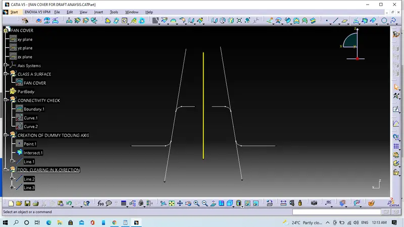
5. We will use the bisecting method to find the tool clearing in X-direction. For that we will follow some steps for bisecting method.
(a) First thing we have to select two points on the lines which are approximately parallel to tooling axis and create the line. Same thing we have to do on other side of the dummy tooling axis as well.
(b) After that we have to create a line by selecting bisecting option in line creation dialogue box.
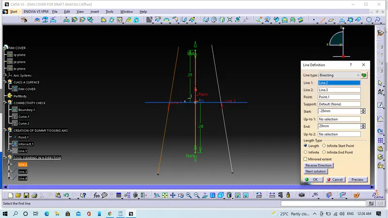
6. Tool clearing in Y-direction: Insert the axis system, take the intersection of plane and the surface.
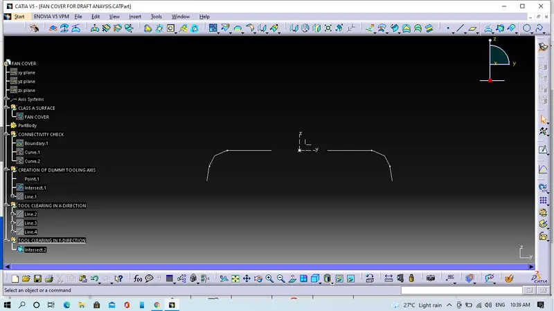
7. We will use the bisecting method to find the tool clearing in Y-direction. For that we will follow some steps for bisecting method.
(a) First thing we have to select two points on the lines which are approximately parallel to tooling axis and create the line. Same thing we have to do on other side of the dummy tooling axis as well.
(b) After that we have to create a line by selecting bisecting option in line creation dialogue box.
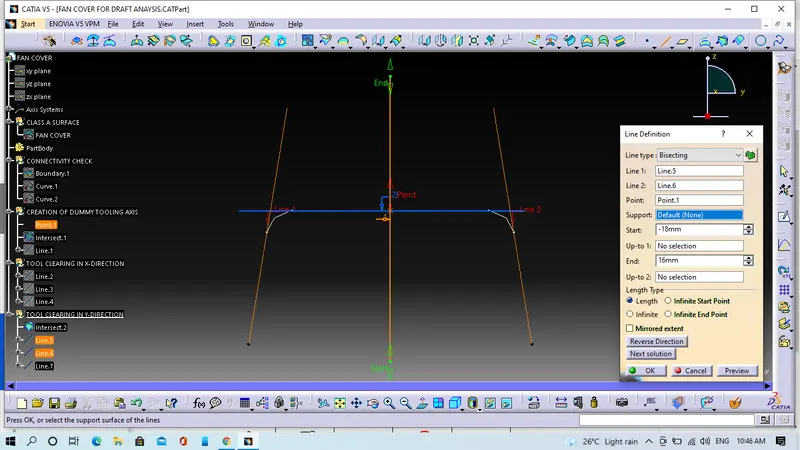
8. Now we will create actual tooling axis, for that a line will create by bisecting tool clearing in X and Y-direction and that will be the actual tooling axis.
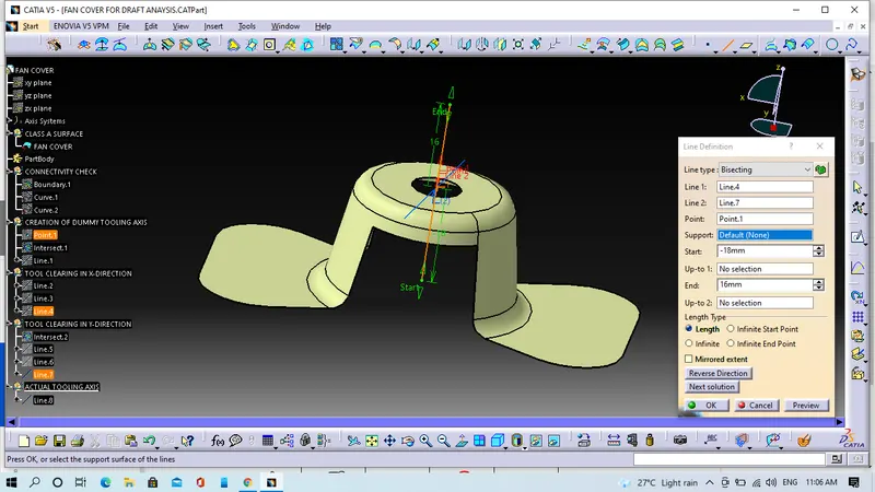
9. Draft analysis:-For draft analysis we have to follow some steps, click on the compass icon, drag it to the tooling axis and align it with the tooling axis. After that we have to customize view parameter mode and select the material option and then we will click on the fan cover surface.
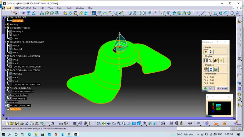
10. Now we will check the degree of the surfaces for that we will go to the features draft analysis toolbar and click the analyses under the running point option after that we move the mouse cursor on the surface it gonna shows how mush degree is their for that specific point. So if the drgrees are ok then it will be ready for design.
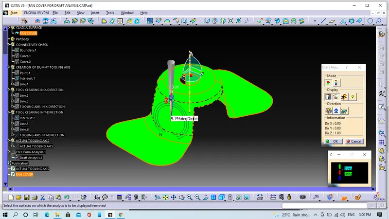
11. Full draft analysis
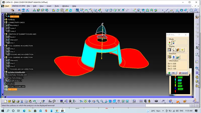
Screenshots of the draft analysis in various orientations (Isometric, Front, Side, and Top View)
(a) Isometric View
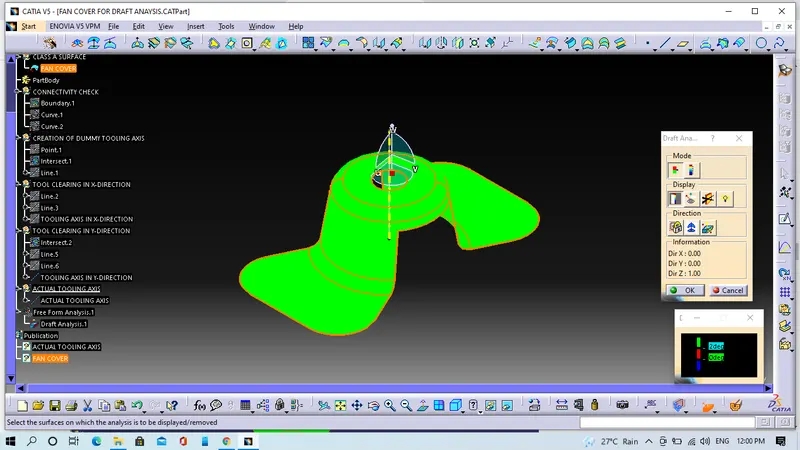
(b) Front View
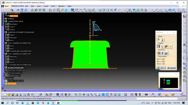
(c) Side View
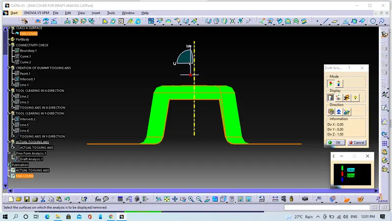
(d) Top View