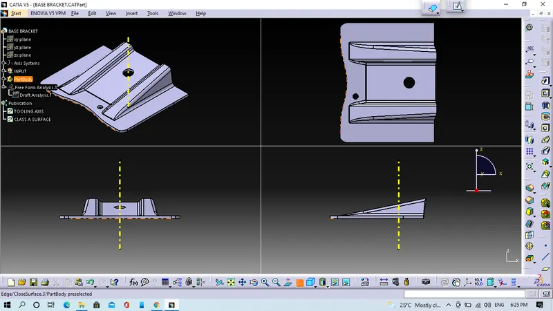
Week 8 - Challenge 2 - Base Bracket Design
Objective:- We will create a Base Bracket plastic component by the help of given Class A surface and after that we will do draft analysis on this component.
Basic introduction about Draft, Draft angle and Draft analysis
Draft:- Draft is the amonut of taper for moulded or cast parts perpendicular to the parting line.
Draft angle:- Draft angle is a taper applied to the vertical to assist with releasing the part from the mould.
Draft analysis:-The Draft Analysis command enables you to detect if the part you drafted will be easily removed. This type of analysis is performed based on colour ranges identifying zones on the analyzed element where the deviation from the draft direction at any point, corresponds to specified values. Most parts or applications require a minimum of half to one degree. However 3 degree is widely accepted as per the norms.
Steps for draft analysis on base bracket model
1. First we have to check the connectivity of the class A surface. After that we will check on join command and we will see how it will connected for just ensure that no surface gap between the surfaces and by the extracting of given class A surface we can visually check the connectivity of the base bracket model.
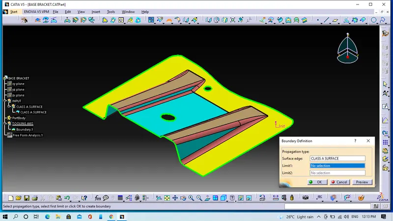
2. Create an axis system at the big hole.
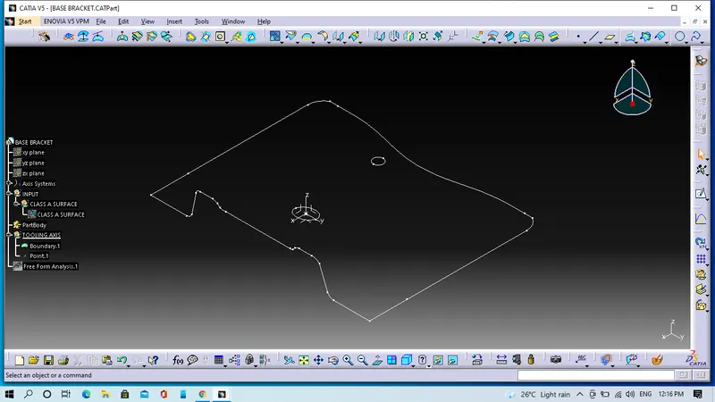
3. Then we will decide the component ejection direction and we will set the dummy tooling axis. Dummy tooling axis is the line along which core and cavity will open.
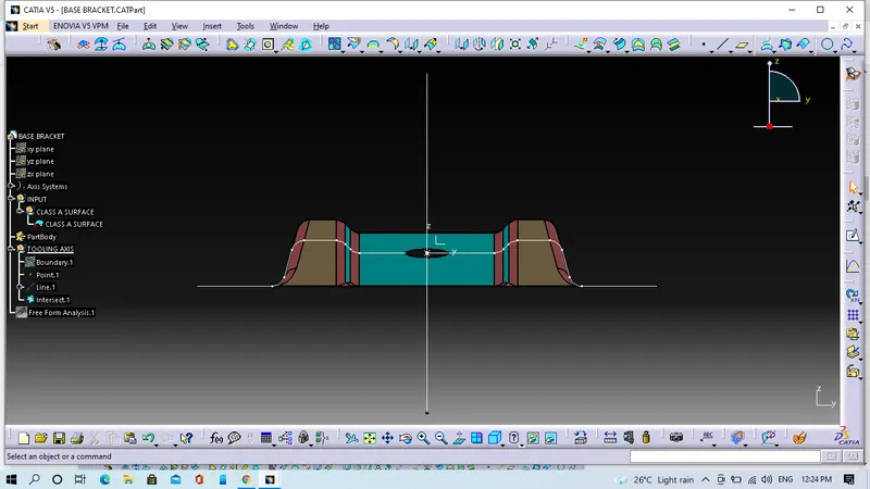
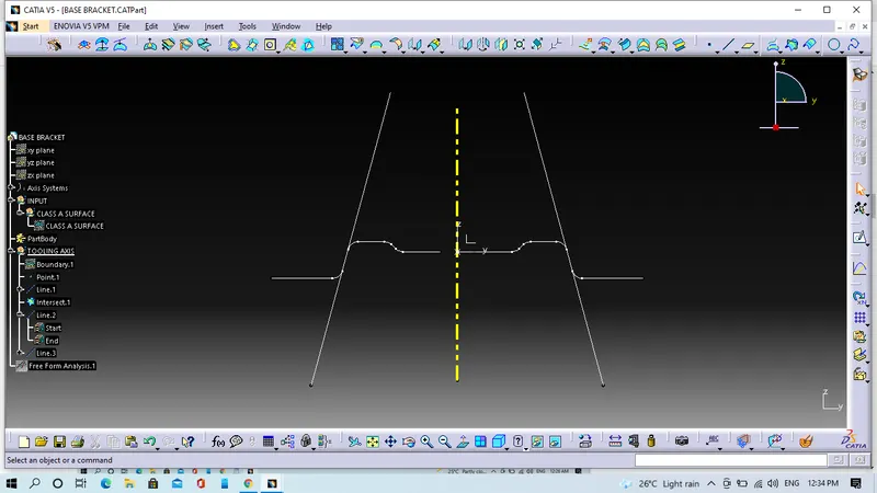
4. After that we will create actual tooling axis by the help of bisecting method. Now find the lines lying approximately parrel to dummy tooling axis. These should be the lines along which draft angle is provided. Select two point on the intersection line and then obtain the line as shown in the below image.
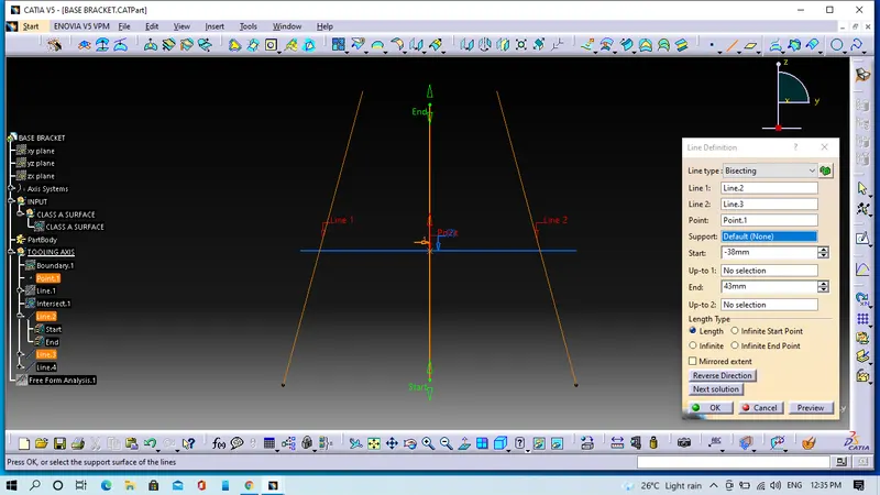
5. Then we will create new line by the help selecting bisecting option in line creation dialogue box and this will be the actual tooling axis for this base bracket model.
6. So now we are in final stage of draft analysis. But for draft analysis we have to follow some steps, click on the compass icon, drag it to the tooling axis and align it with the tooling axis. After that we have to click in option of customize view parameter mode and select the material option and then we will click on the base bracket surface.
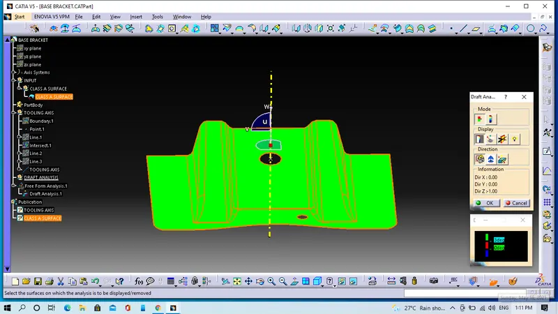
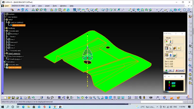
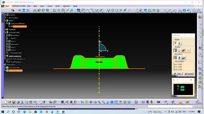
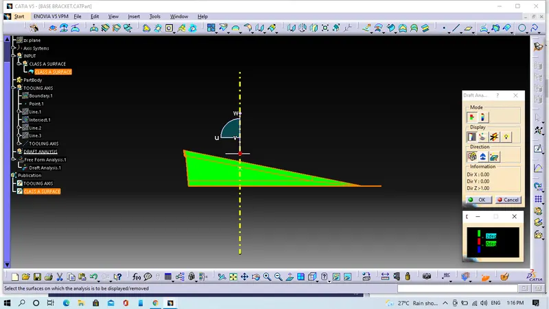
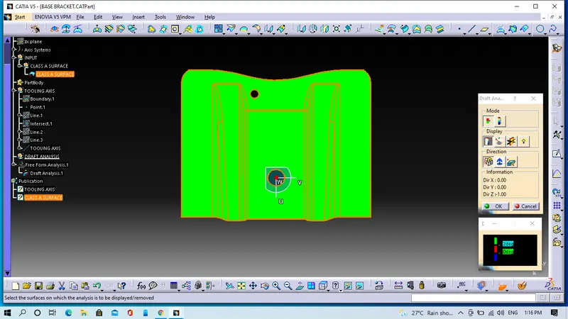
In the above image we can see that the surface is green colour has draft angle greater than 2 degree and which is most required for tooling feasibility.
7. This image is showing full draft analysis.
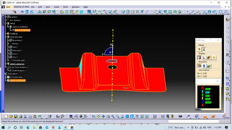
Draft angle in various orientations (Isometric, Front, Side, and Top View)
Isometric View
Front View
Side View
Top View
Next we will create B and C surface by the help of given class A surface
For that we have to follow some steps
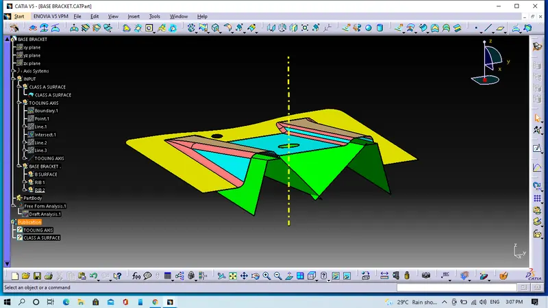
1. We will create Two Rib surface offsetting the same to a value equal to the thickness of the component.
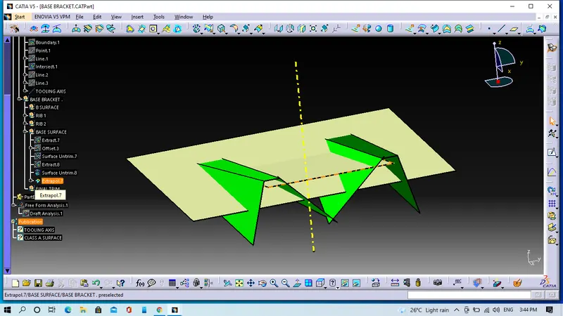
2. Now we will create Base surface.
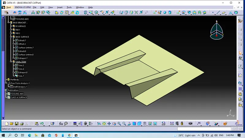
3. After that we will go for trimming operation for carried out to get the required class B surface.
4. Now we will create C surface by the help of sweep command.
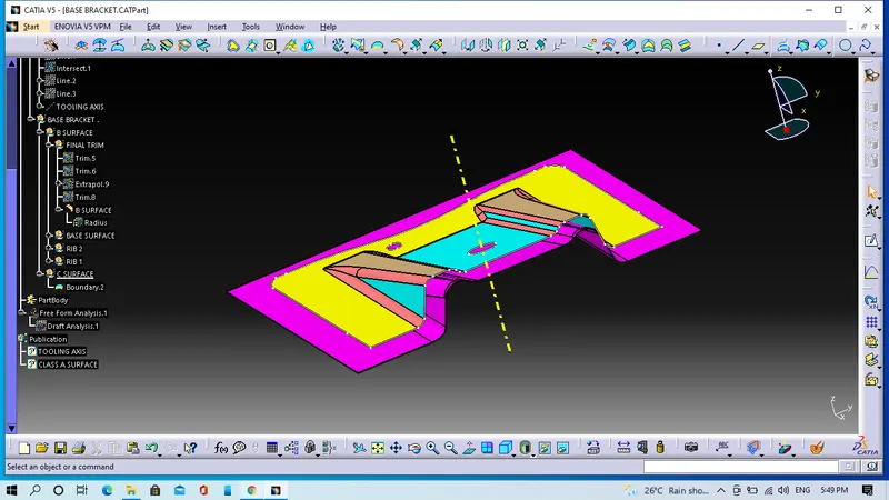
5. Final stage
In the final stage we will do final trim and we get required model.
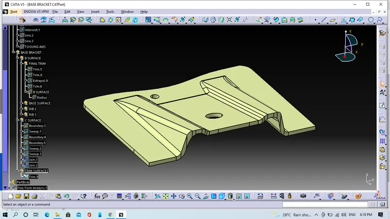
And this below image is showing close surface model
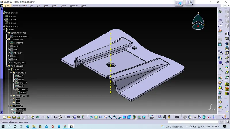
Close surface model has various orientations (Isometric, Front, Side, and Top View)