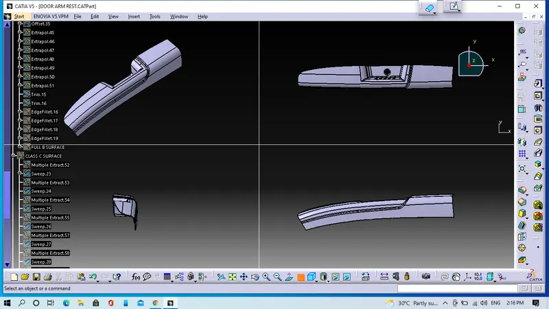
Door Arm Rest Week 8 Challenge
Objective:- To create B & C surface for the given Class A surface and we will add thickness to it.
Note:-This model is little bit complex to design with single tooling axis thats why we will take two tooling axis for this model.
1. Creation of tooling axis
- Creation of first Tooling
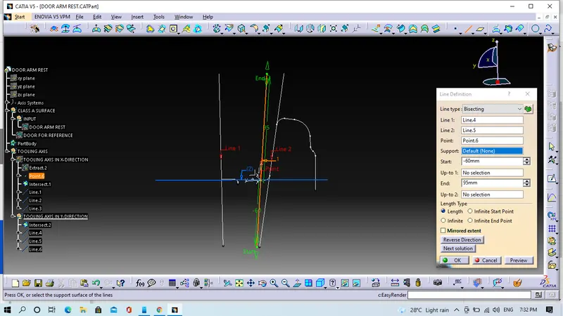
We will extract the base surface, create on point on it and insert the axis system at the point created. To get intersection curve in the XZ plane and in the model, we will draw two intersection curve after that we will go the bisecting option to get tooling axis.
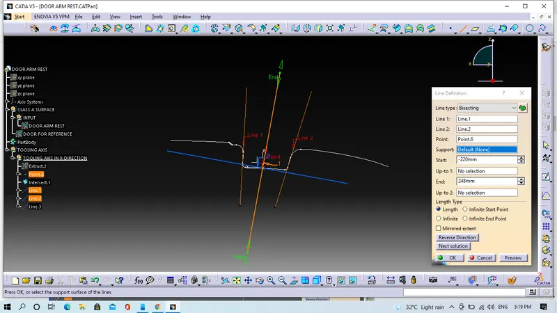
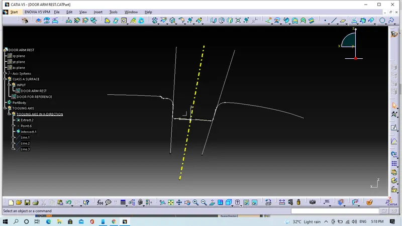
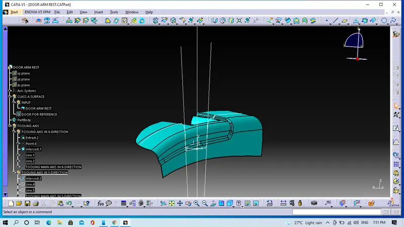
- Creation of second tooling axis
We will extract the base surface, create on point on it and insert the axis system at the point created. To get intersection curve in the YZ plane and in the model, we will draw two intersection curve after that we will go the bisecting option to get tooling axis.
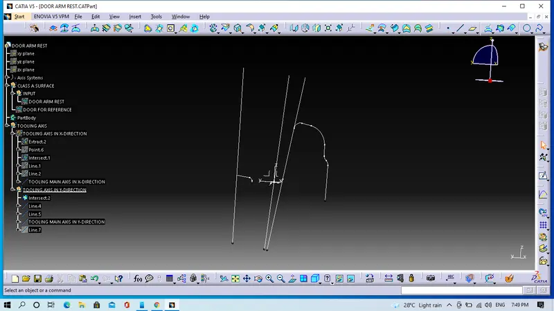
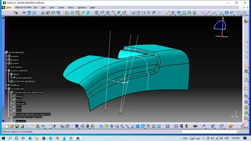
- Creation of actual tooling axis
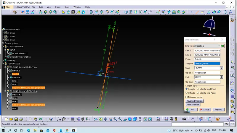
Get a actual tooling axis, we will use bisecting option between tooling axis in X-direction and Y-direction.
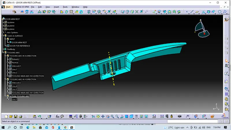
2. Now we will perform on the draft analysis
For draft analysis we have to follow some steps
- Click on campus icon, drag it to the tooling axis and align it with the tooling axis after we have to click customize view parameter mode and select the material option and then we will click on the surface.
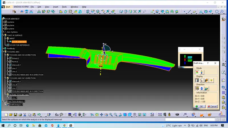
In the above image we cam see that the surface is green colour surface has draft angle greater than 3 degree and which is the most required for tooling feasibility.
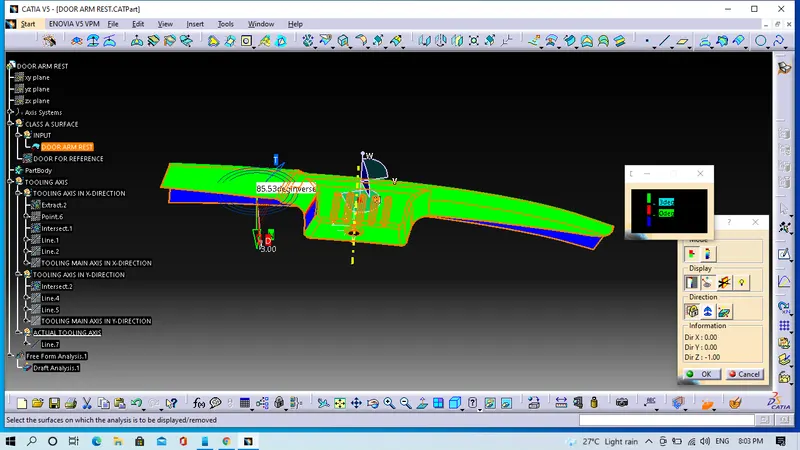
- Now we will check the degree of the surface for that we will go to the features draft analysis toolbar and click analysis under the running point option after that we will move the mouse cursor on the surface it gonna shows how much degree is their for that specific point. So if the degree is same as required in the model then it will be ready for design.
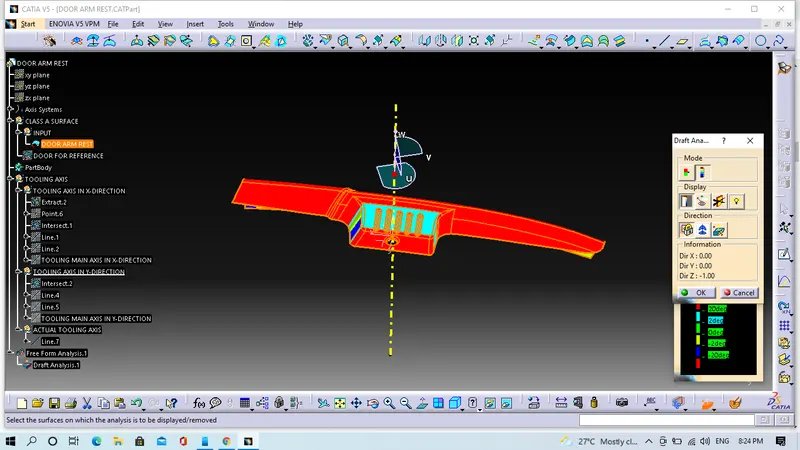
- This image is showing Full draft analysis
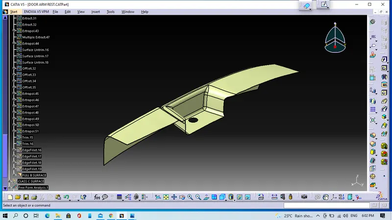
3. Creation of B-Surface
We will extract the top surface and untrim them.
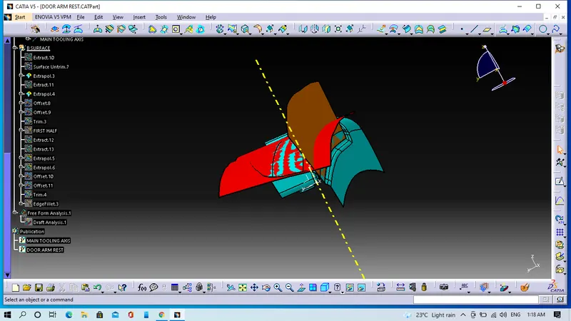
- We will offset them to a value equal to the thickness of the model and trim the unwanted edges.
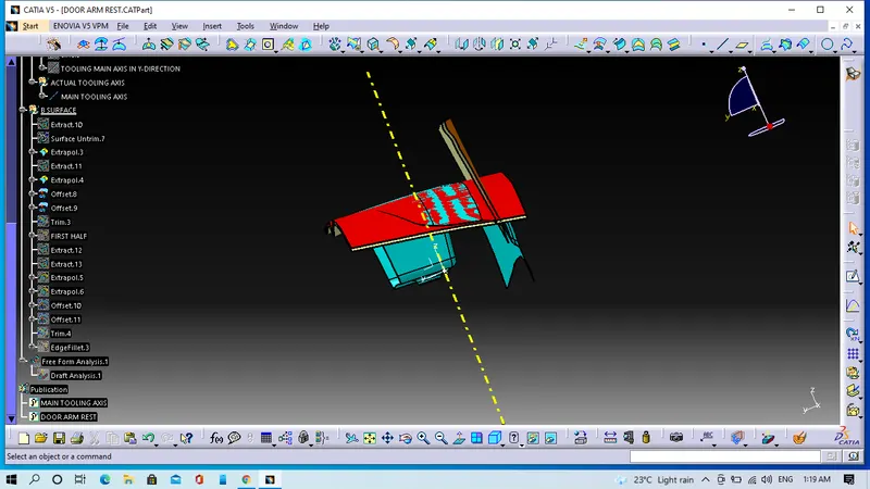
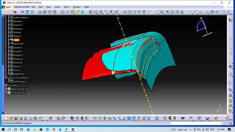
- After that we will apply fillet value on it.
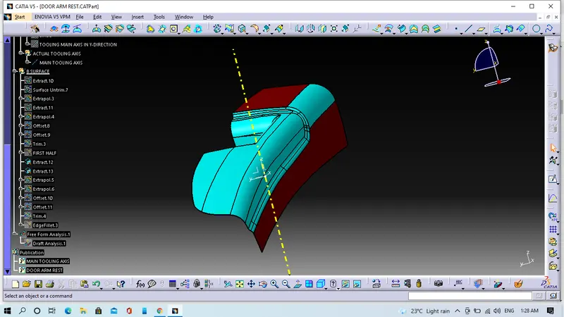
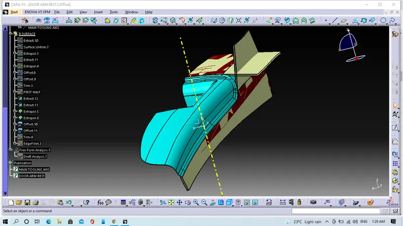
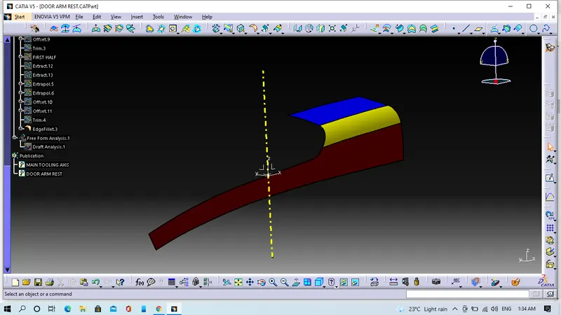
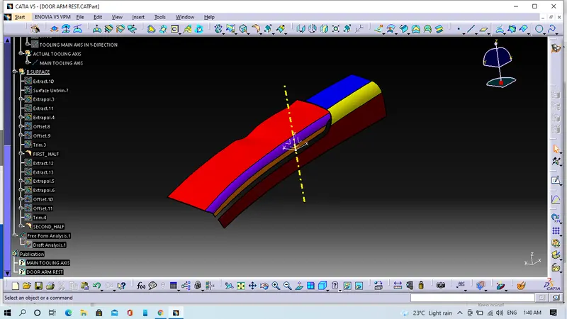
- Formation of side filleted edge
We will insert axis system at the intersection point as shown in the image, click on the intersect with 3D element, get the intersection line after the draw a line with tangency constraint to this intersection curve then by the help of multiple extract cammand we will get the guide curve then we will click on smoothing curve option after that we will use sweep command to get the surface.
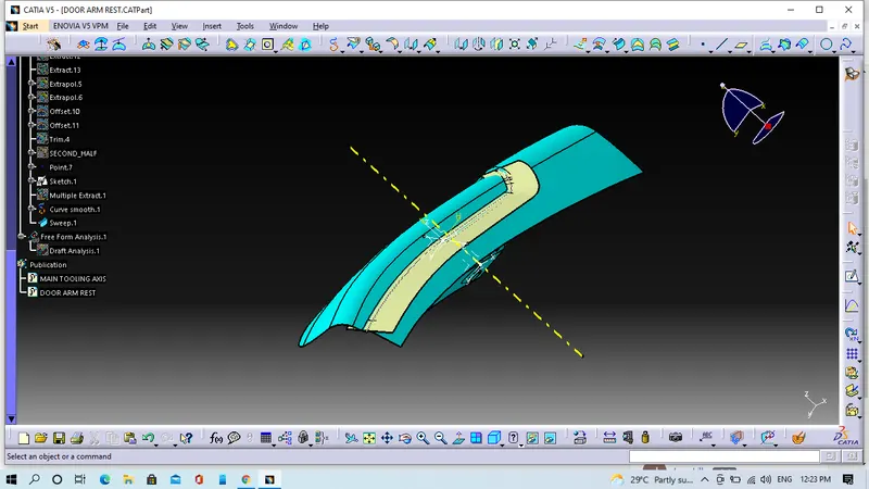
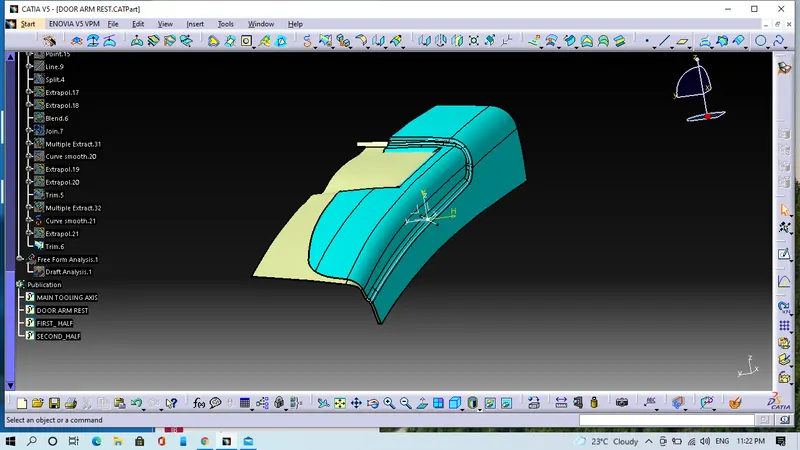
Similarly we will extract the Base as well as side surface of the model, will trim it,will offset it and finally we will give fillet value on it.
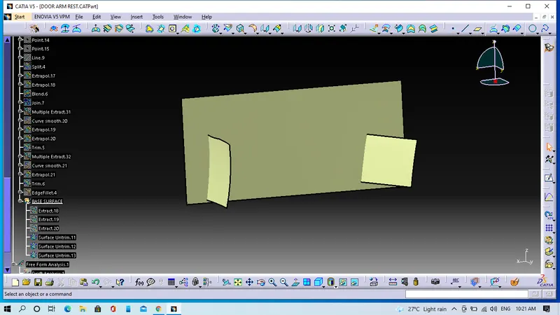
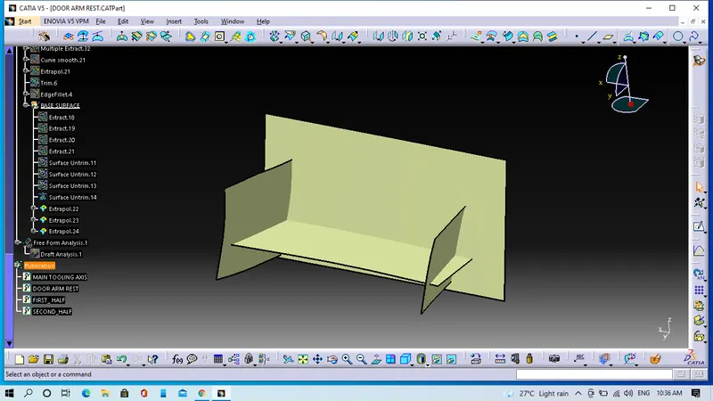
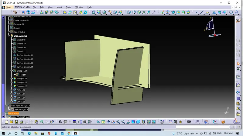
4. Creation of C-Surface
For C-Surface creation we have to perform some steps
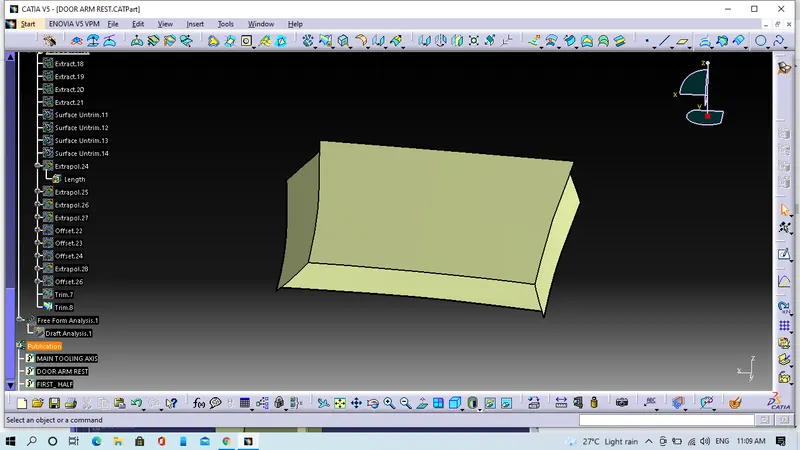
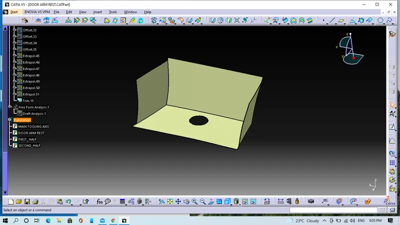
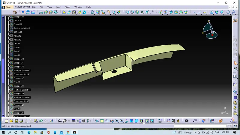
We will use sweep with draft direction command, sweep reference to surface and join command as well.
5. Final operation
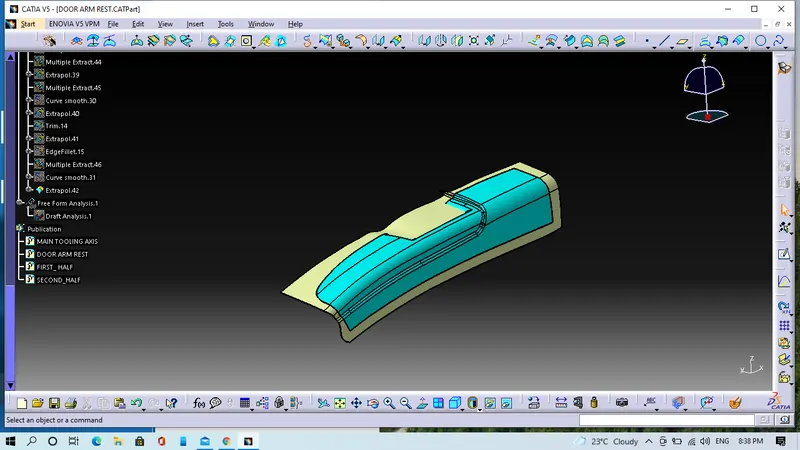
We will join the Class-A and Class-C and trim with Class-B.
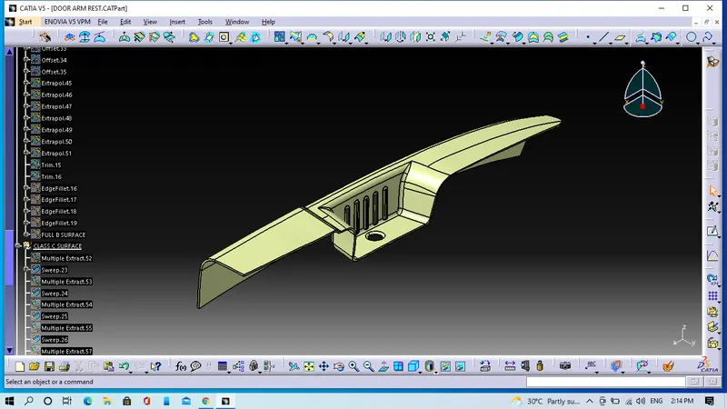
Screeenshots in various orientation
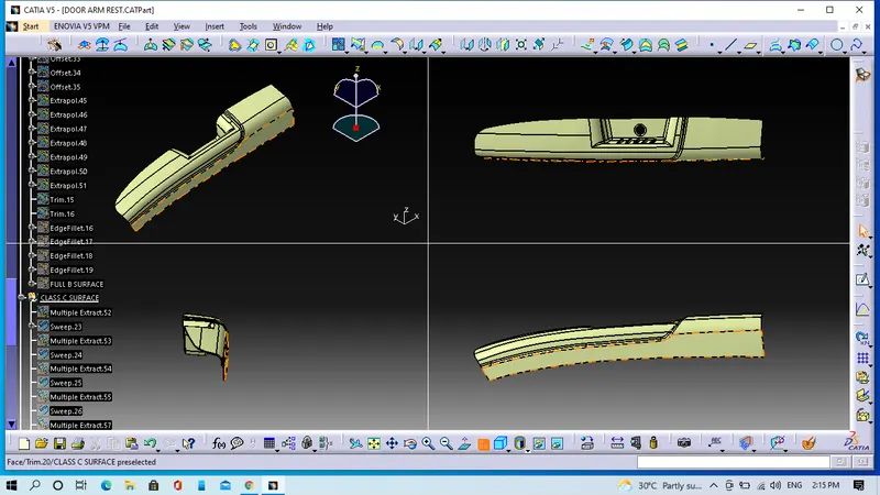
To make solid body
We have to move to the part workbench, define the object in the part body and close it.
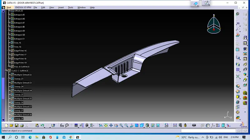
Screeenshots in various orientation