Week 8 - Challenge 5 - Core & Cavity Design
AIM:-
To perform draft analysis on switch bezel design with the help of tooling axis. by with the help of the class A surface, we will make class B and class C surfaces and by making all of them we will go for the construction of the core and cavity for the plastic module switch bezel.
Objective:-
Our main objective is to construct the core and cavity for the A-class surface. that can only be done by creating class B and class C surface with the help of class A surface and with the help of the tooling axis. the tooling axis will only create by the bi-section method.
Procedure:-
So first we will visualize the whole class A surface if there is any kind of opening. after visualizing it we will go for the best direction to make a tooling axis. first, we will check in the Y-direction.
Creation of tooling axis in Y-direction.
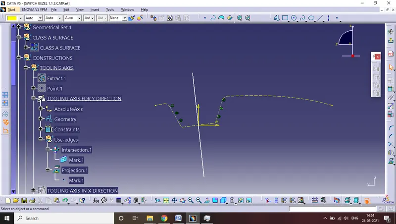
we will extract the base of the switch bezel and then we will use an axis system to create a plane. then we will use the projection command on class a and get the two lines for the creation of the tooling axis in the y-direction.
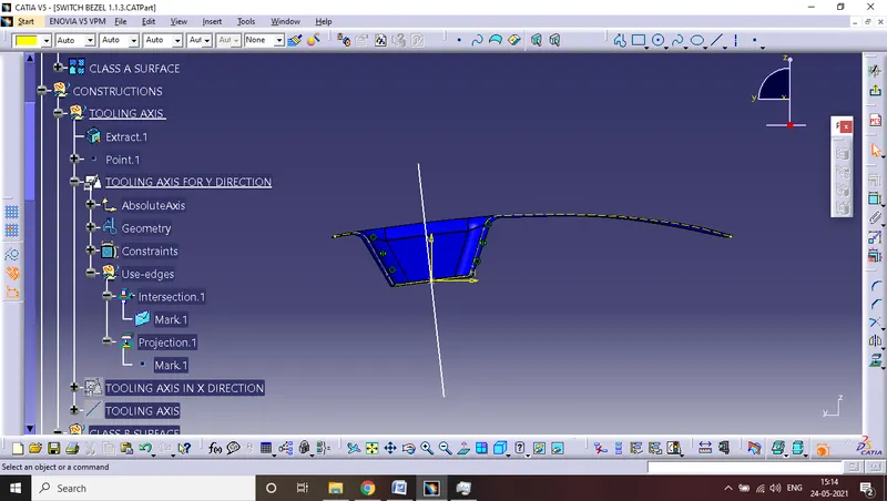
then we will create a tooling axis in the x-direction.
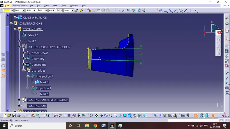
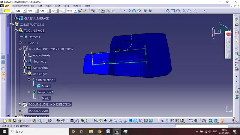
after getting both tooling axis in the x and y direction we will create the main tooling axis with the help of the bisection method.
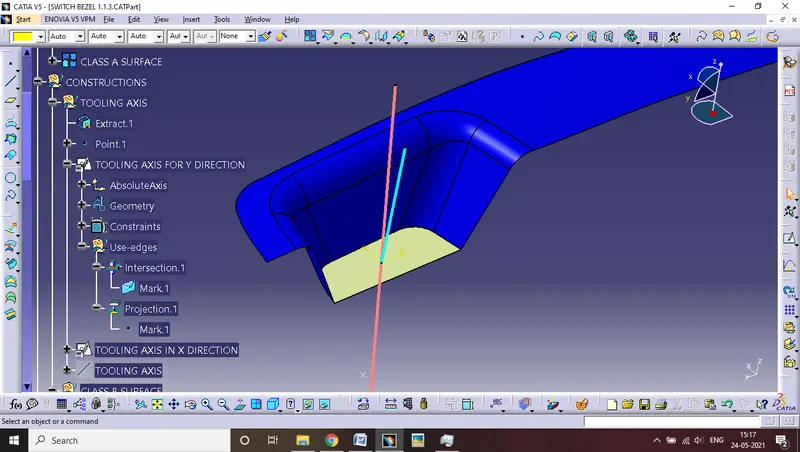
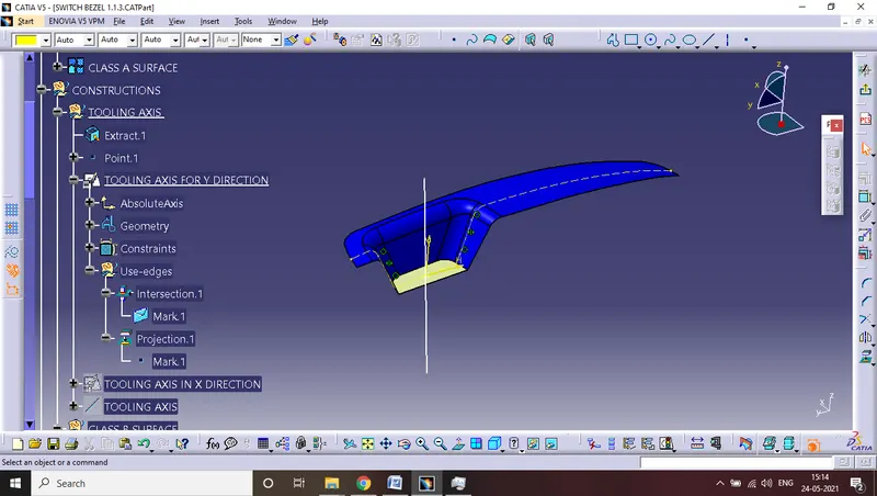
then after getting the tooling axis we will perform the draft analysis.
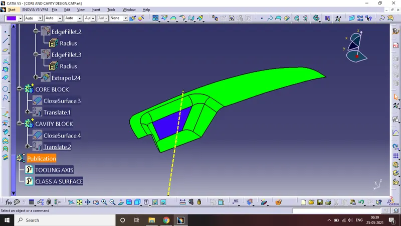
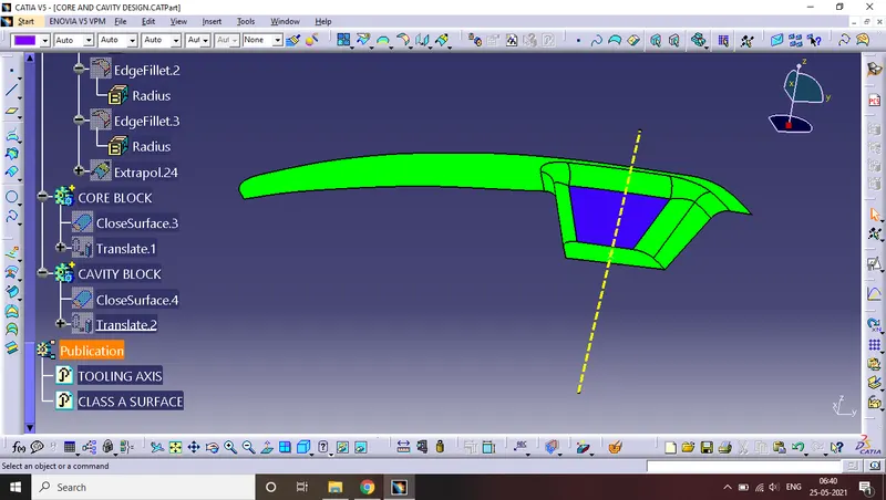
after performing the draft analysis we will create the class b surface
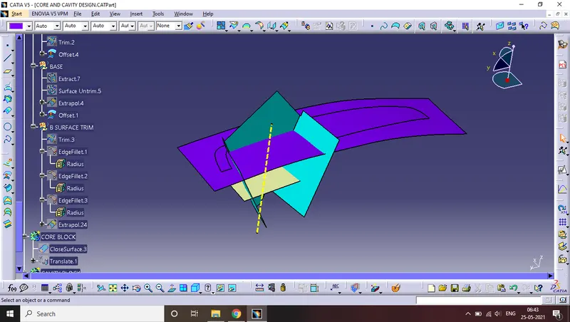
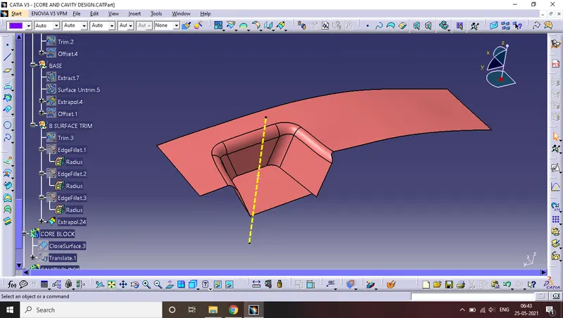
then we will create the class c surface. here we will create a boundary around the class surface and then use the sweep command.
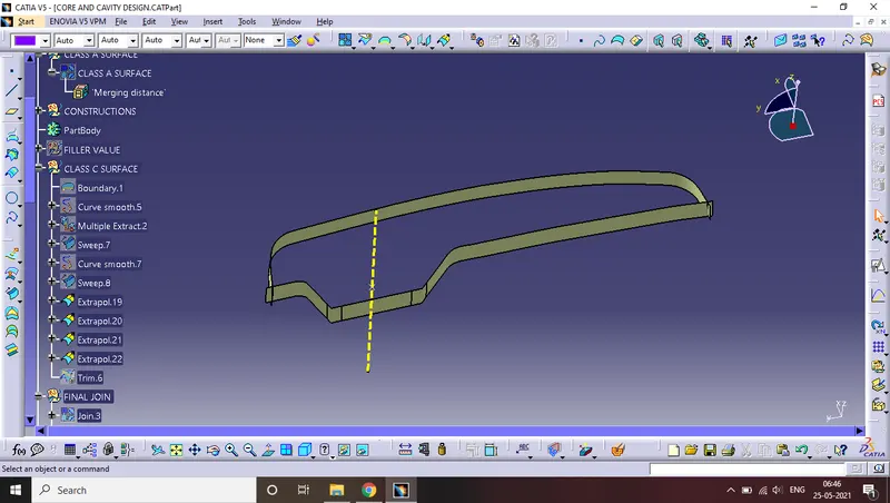
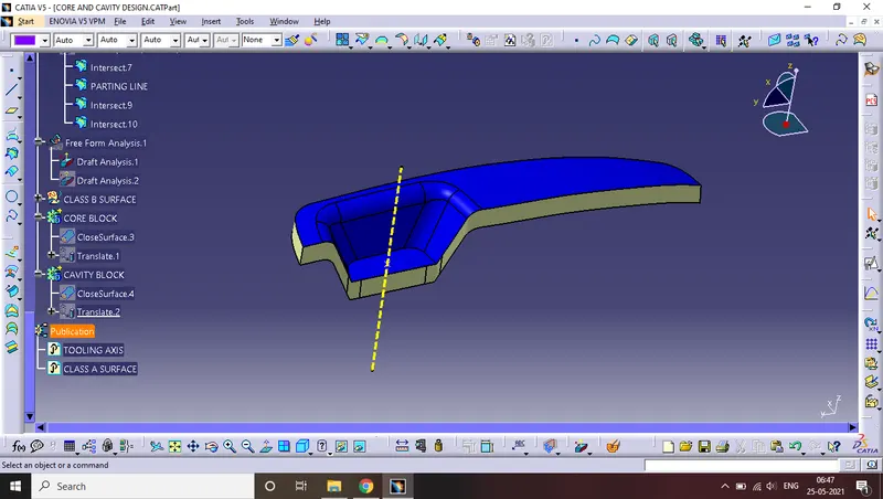
then we will join classes A and C and then trim it with class b surface. this is the output we will get from it.
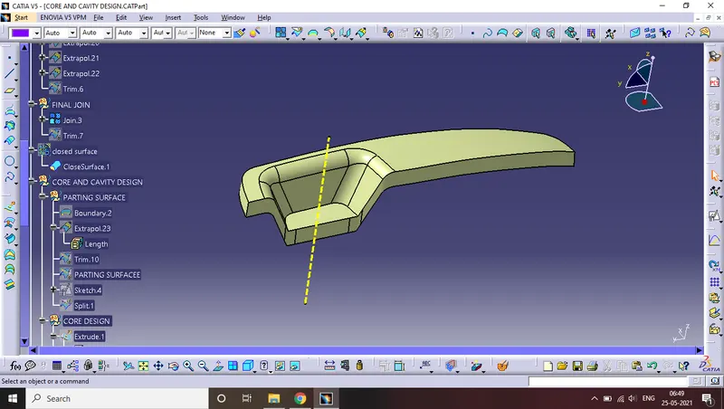
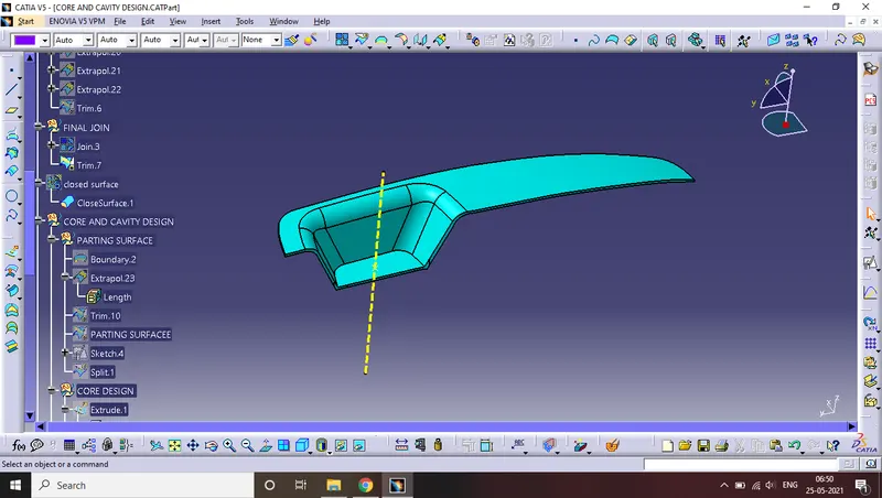
then after creating surfaces we will go for draft analysis.
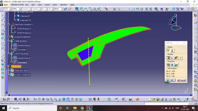
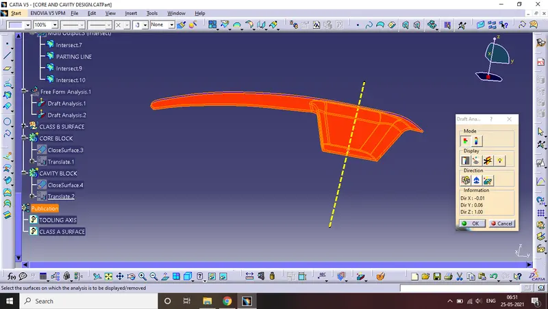
after performing the draft analysis it is time for the construction of the core and cavity.
first, we will create a boundary on the closed surface we created a extrapolate of it.
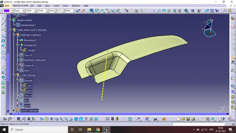
after that, we will trim it with a class c surface.
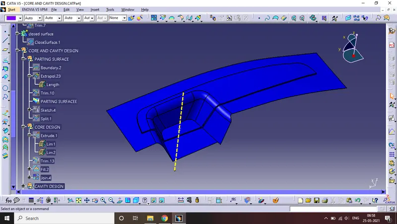
this will be our parting Surface-
PARTING SURFACE:- it is the surface that connects the core and cavity.
then we will go for core design.
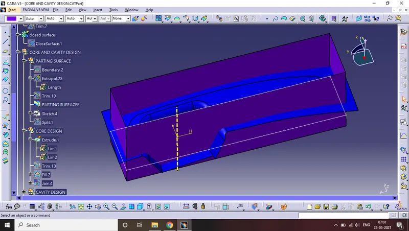
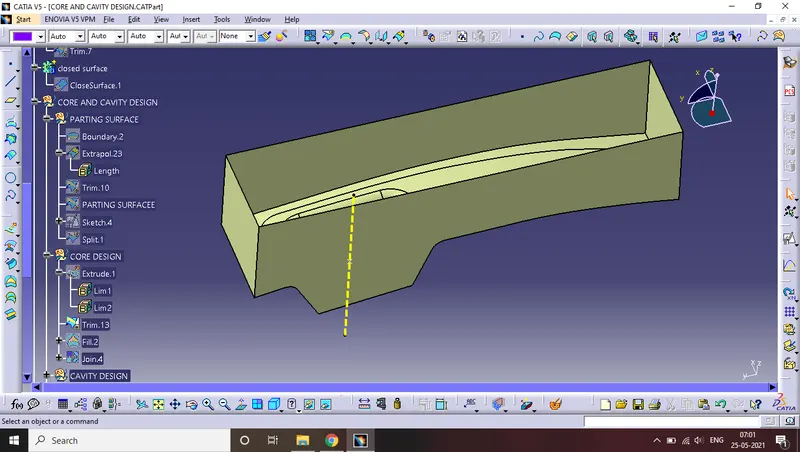
then we will create a cavity by the same extrude.
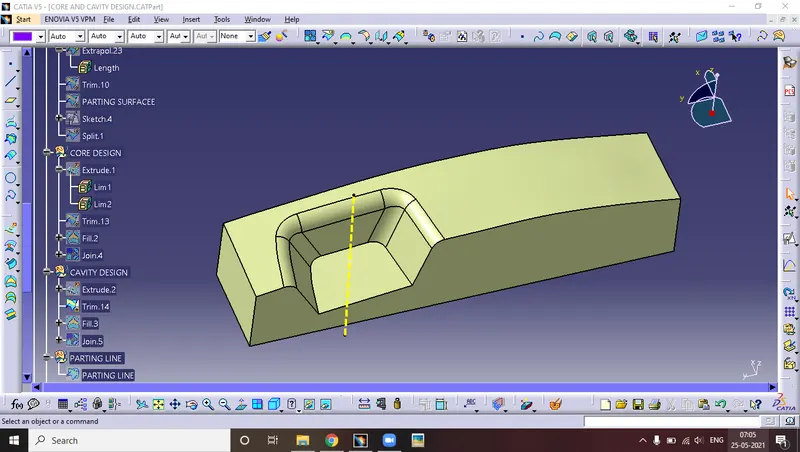
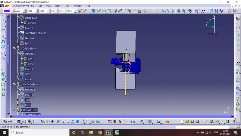
Parting line:- it is the intersection between the parting surface and the component that where the core and cavity move from each other.
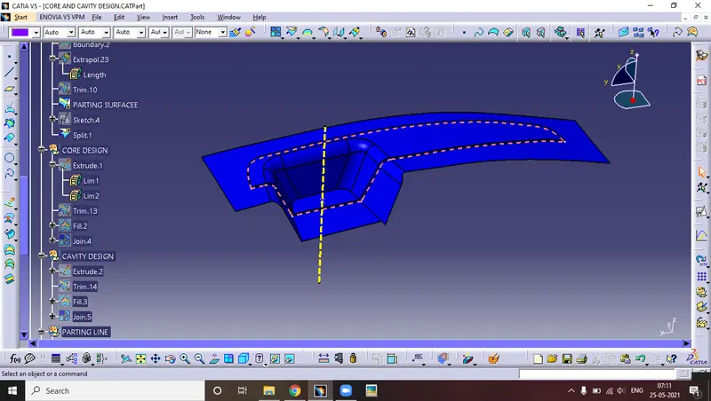
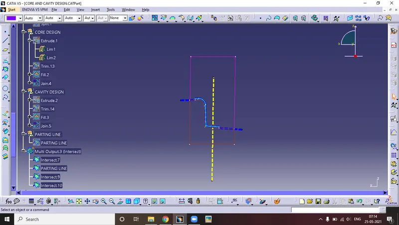
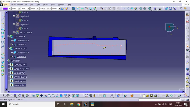
These are the intersection of core and cavity and the parting surfaces.
then with the help of the intersection command, we will create the core and cavity at a certain distance.
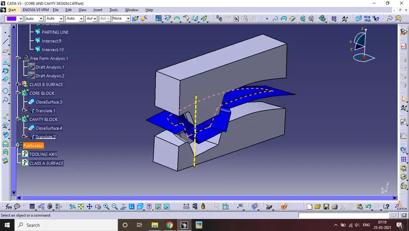
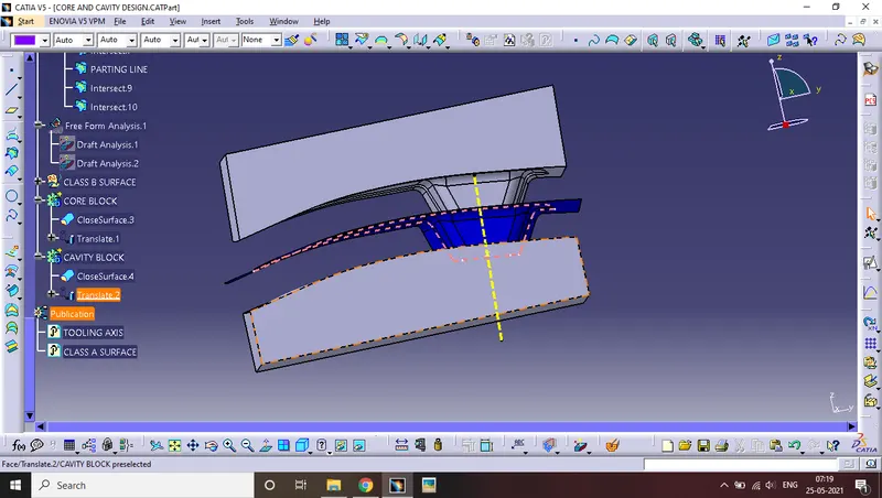
Isometric view
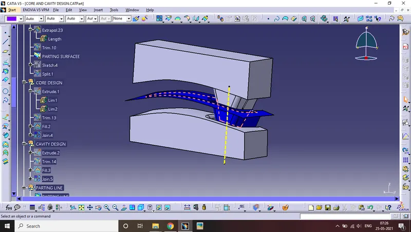
front view
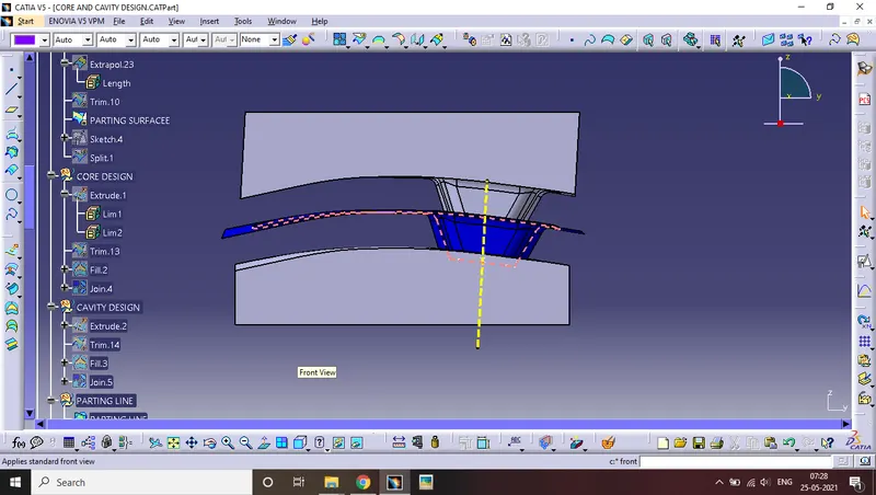
side view
top view