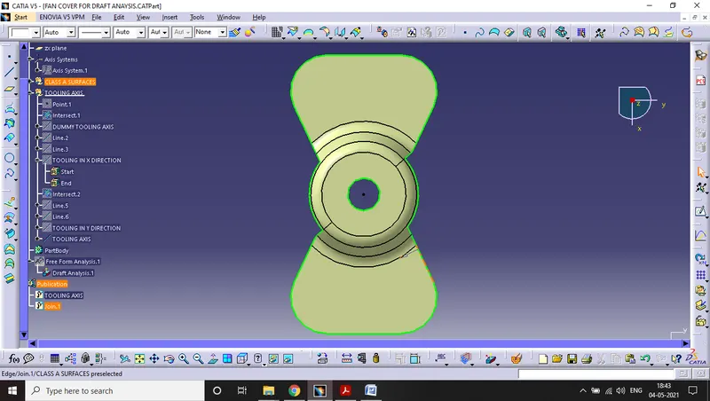
Week 8 - Challenge 1 - Draft Analysis on a Fan Cover
AIM:-
TO PERFORM DRAFT ANALYSIS ON FAN COVER
OBJECTIVE:-
THE objective is to perform draft analysis by creating a tooling axis for a Fan cover.
With the help of the tooling axis, we have to perform a draft analysis on a fan cover.
Procedure:-
- Design check
First of all, we have to check the design of Class a surface by inspecting the whole component. We use the join command to check the connectivity of the component. Then we check the gap between the surfaces if it is good then we proceed to the next step. Then we use the boundary command to check the boundary part it will show multiple outputs. After these, we use disassemble command to disassemble the component. Then we have two boundaries. So here the first design check is completed.
- Dummy Tooling Axis Creation
TOOLING AXIS: The direction in which the core and cavity open.
The analysis of the fan cover is important. We analyze which is the best direction for the fan cover by checking the symmetry of the component. Then we found out that the best direction will be the Z direction. In the Z direction, we found that the core and cavity will move easily. So the tooling axis will in the Z direction.
With the help of the intersection command, we create the section of the component with help of the Axis system.
Here is the output of the section part.
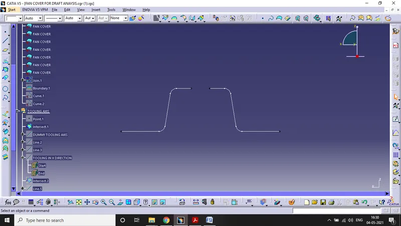
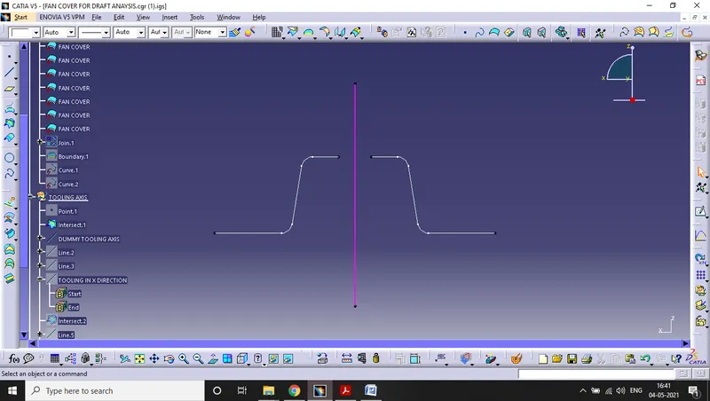
With the help of line command, we will create a line in a center which will be a dummy tooling axis and its direction will be the z.
3. The creation of tooling axis in the X direction by using BI-SECTION METHOD
After creating a dummy tooling axis we have to extend the inclined walls.
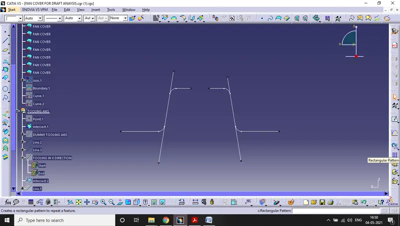
The purpose of extending this line is to create a tooling axis. after creating a tooling axis we have to use the bisecting option in the line command to create a bisection line. there will be a line formed which will be the tooling axis in the X-direction.
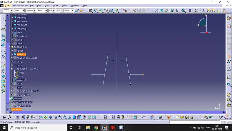
4. The creation of tooling axis in the Y direction by using BI-SECTION METHOD
Again we use the intersection command we use YZ plane to create a section.
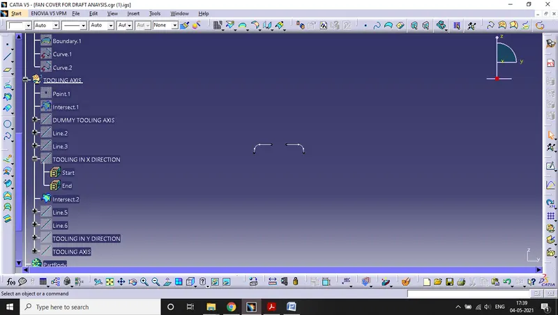
then with the same method, we will extend the inclined lines which will be parallel to the tooling axis.
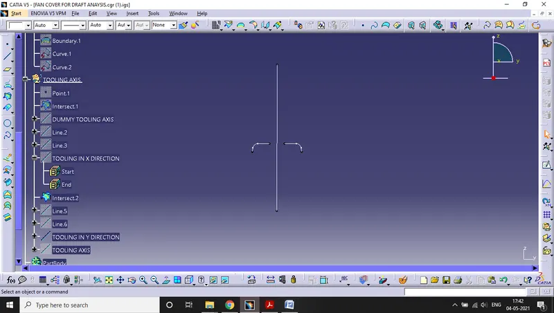
5. The creation of actual tooling axis with the help of tooling clearing on x and y-direction by using bisection method again.
Now we have created both tooling axis in x-direction and y-direction. We will use the bisection method and create a tooling axis for the component with the help of the earlier tooling axis we created.
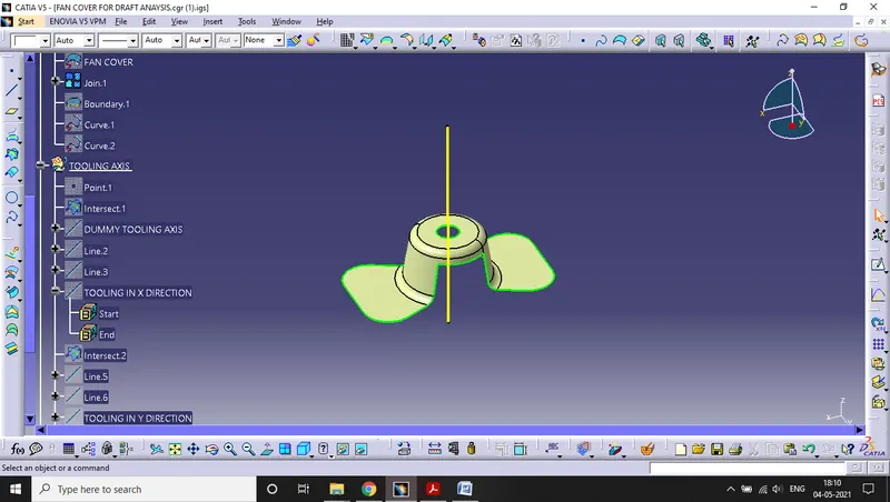
Now we will publish both the Tooling axis and class A SURFACE.
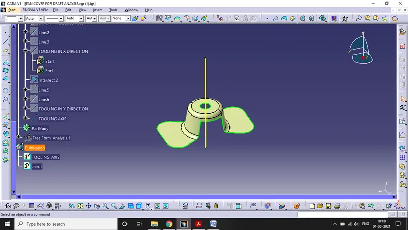
NOW WE HAVE CREATED THE TOOLING AXIS NOW WE CAN PERFORM DRAFT ANALYSIS.
The minimum draft degree is required for design is 3 '.
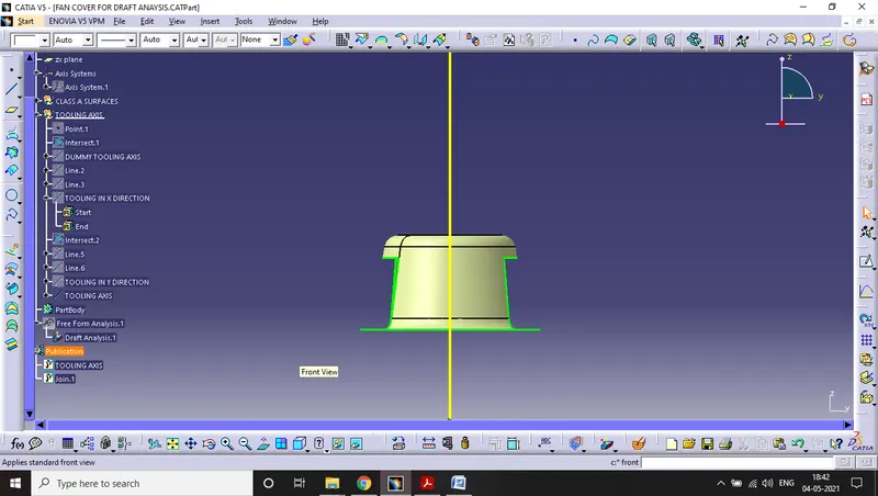
We pick the compass from the draft analysis tool and put on the tooling axis . and then perform the draft analysis.
if the component turned green then our design is good to go for production.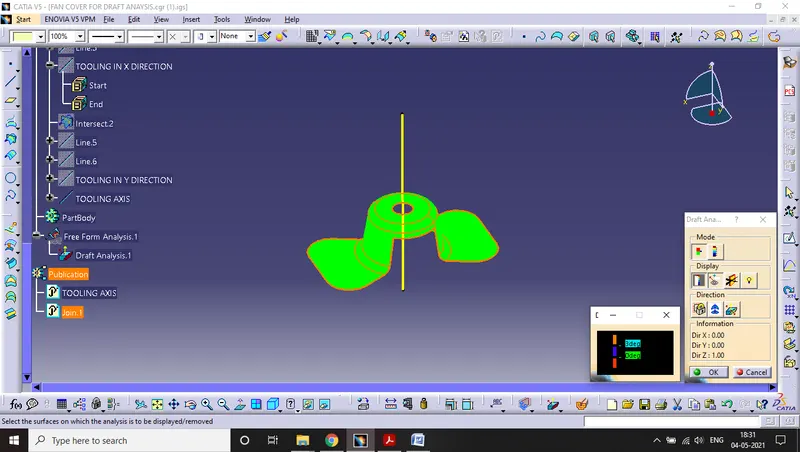
Let's changed the angles and see the result. we take the degree as 12.
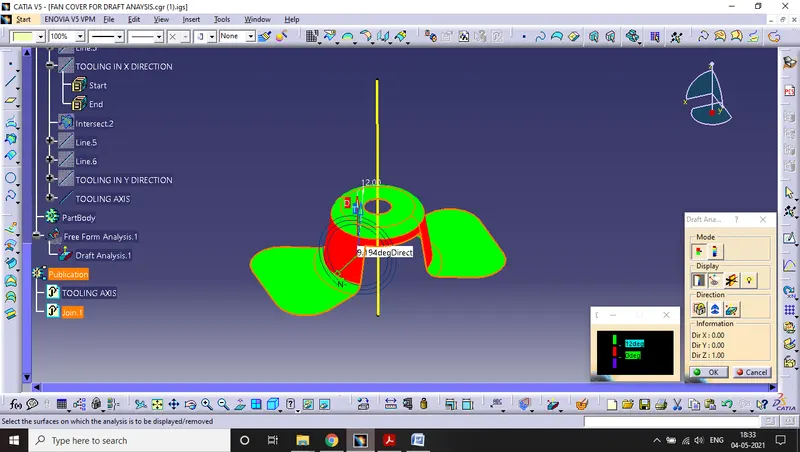
it is not fit for design so the 3 degree is the only angle that is best for the draft angle.
ISOMETRIC VIEW
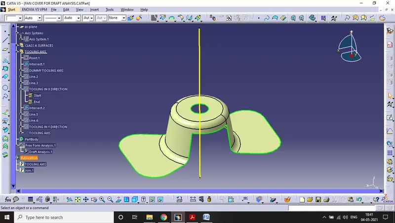
FRONT VIEW
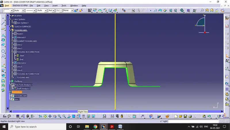
SIDE VIEW
TOP VIEW