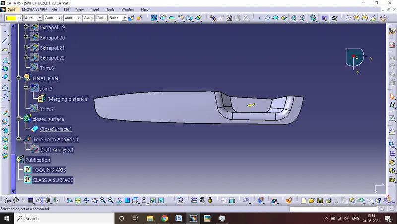
Week 8 - Challenge 3 - Switch Bezel Design
AIM: -
To perform draft analysis on switch bezel design by combing class A, B, and C surface b using tooling axis.
OBJECTIVE: -
The main objective is to perform draft analysis with the help of using class a surface then with the help of class surface we create the class b surface and class c surface.
after creating class a, b, and c surfaces we will trim and join them to create a single component for draft analysis.
And then we will create our tooling axis with the help of the bisection method.
Procedure:-
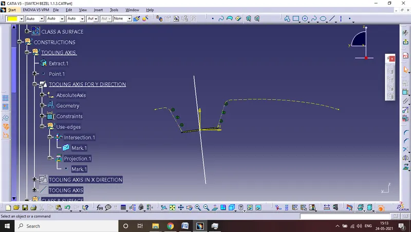
First, we will join all the parts of class a surface into single component .that is our main class a surface where we perform the upcoming operations. after that we check for is there any gap then we will go to the join command and check it properly. Then we will visualize the whole class for better tooling axis direction. then we go for the creation of the y-axis. Then we see that all the parameters are good for designing the tooling axis. first, we extract the bottom part of the class a surface then create a point over there in the centre and create an axis system for the creation of the tooling axis. then we project the whole class A surface.
the creation of the tooling axis in Y-direction.
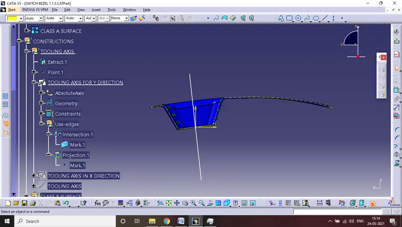
The same goes for the tooling axis in the x-direction.
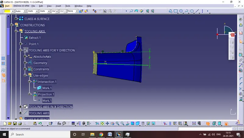
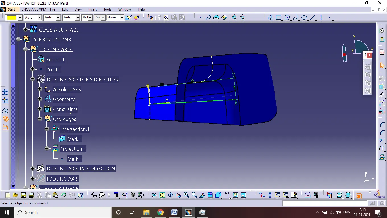
then after creating the tooling axis in X and Y direction we will get two tooling axis .
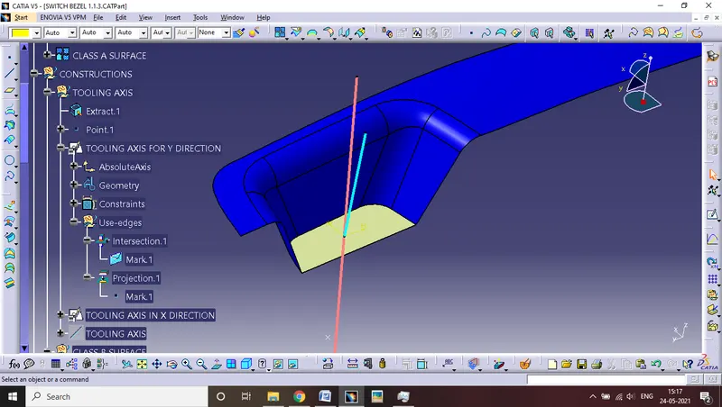
We will use the bisection method to create our main tooling axis.
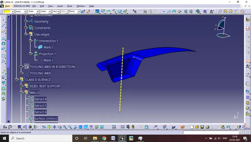
After the creation of the tooling axis, we will go for the creation of the class b surface. step by step we extrude and extend class a surface and then trim it.
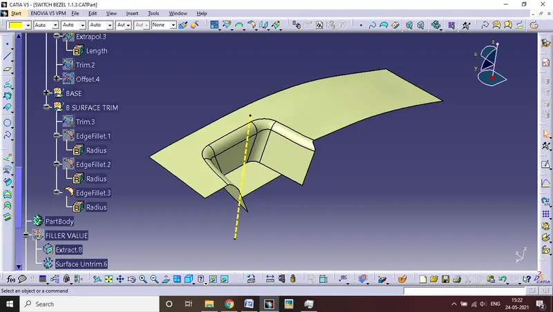
the thickness between CLASS A SURFACE AND CLASS B SURFACE IS 2.5MM.
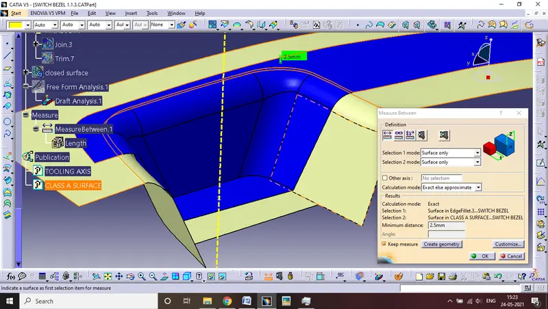
after creating class b we will go for the class C surface. the creation is only possible with the help of the sweep command.
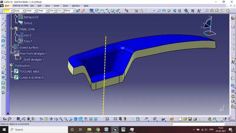
then we will join class A and C surface with the help of the join command. then there is a problem that occurs due the curve is not smooth there are multiple patches are forming so we will use the curve smooth command to smoothen the curve and then we use the join command to increase the thickness to 0.003 because it is the standard value for the plastic design.
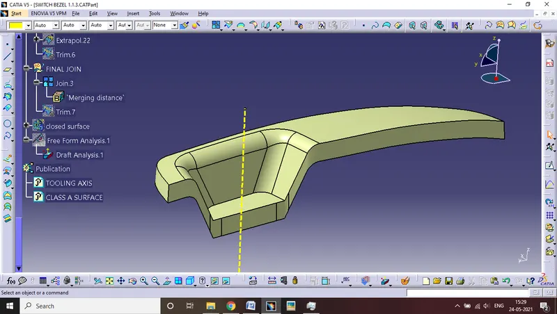
then after joining A and C we will go for surface b and trim with the join of A and c.
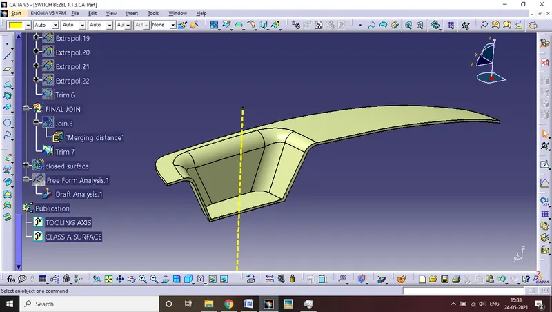
Closed surface
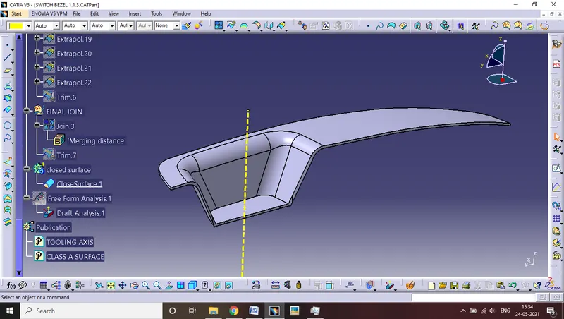
then with the help of the tooling axis, we will perform the draft analysis.
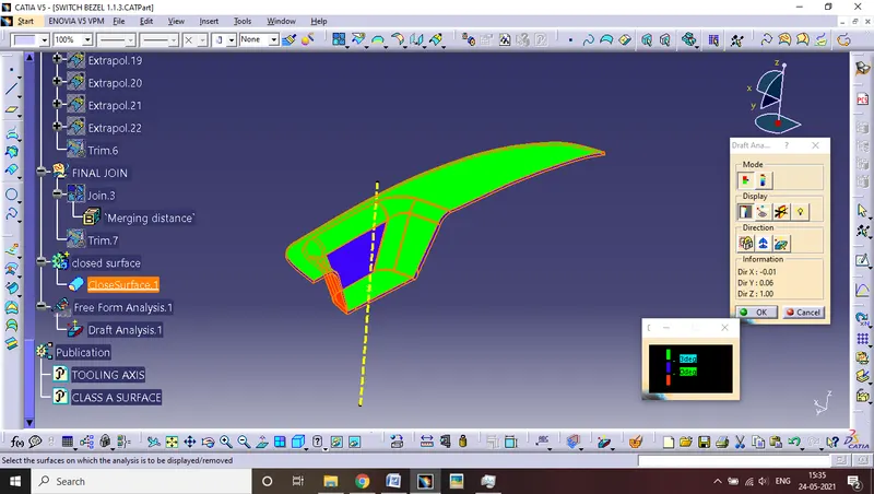
Isometric view
front view
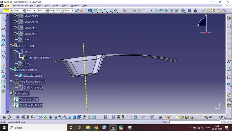
side view
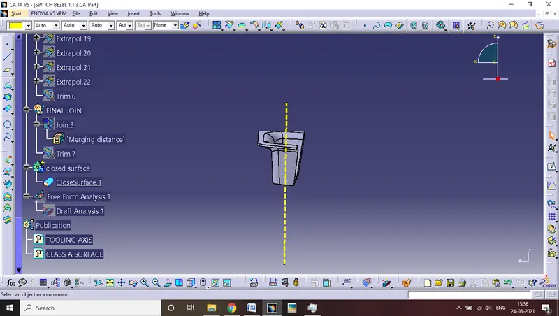
top view