Week 8-Challenge
3D Tetra Meshing
Objective : To mesh the given components using tetra mesh for the given quality criteria.
Procedure : There are a few steps to be followed to tetra mesh the given Models.
Step 1 ) Import the model into hypermesh graphic window.
Step 2 ) Check weather the model consists of any solids in it.
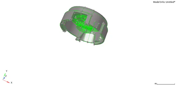
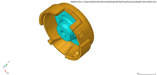
Housing Model :
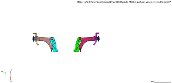
Chasis Assembly :
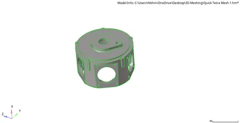
Crank Housing :
There are three methods to do the tetra mesh and these are the following :
- First Method : Conversion of 2D tria elements into 3D tetra elements.
- Second Method : Generating Quick tetra mesh from the 3D tetra meshing panel.
- Third Method : Generating volume tetra mesh from the 3D tetra meshing panel.
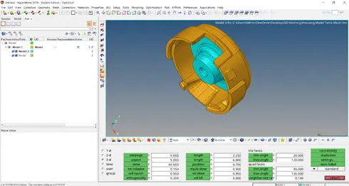
The Housing Model was meshed using the first method.
Step 1 : Import the model.
Step 2 : Check for solids in the model and delete the solids if present.
Step 3 : Check for Topology cleanup areas in the model. If there is any cleanup needed perform it manually.
Step 4 : Perform 2D tria mesh with target element size as 5.
Step 5 : After completing the 2D tria mesh check weather components meets quality criteria from check elements option. If the components does not meet the quality criteria re-mesh or use the tools under quality index.
Step 6 : Now the components are ready to be meshed using 3D tetra mesh.
Step 7 : Now the 3D mesh is completed check for quality criteria that is :
|
Tet Collapse |
0.150 |
|
Minimum Length |
2 |
|
Maximum Length |
7 |
Step 8 : There were no tet collapse failure for this components.
Crank Housing : This model was tetra meshed using second method.
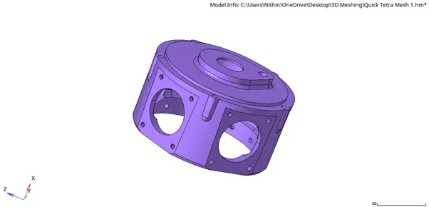
Step 1 : Import the model into the hypermesh window.
Step 2 : Delete the solids if any.
Step 3 : Go to utility panel from the top menu using the “view” option.
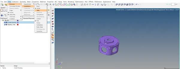
Step 4 : From the utility panel select Geom/Mesh option.
Step 5 : Select “Quick Tetra Mesh” and enter the necessary quality criteria.
Step 6 : The Quick tetra mesh is now completed.
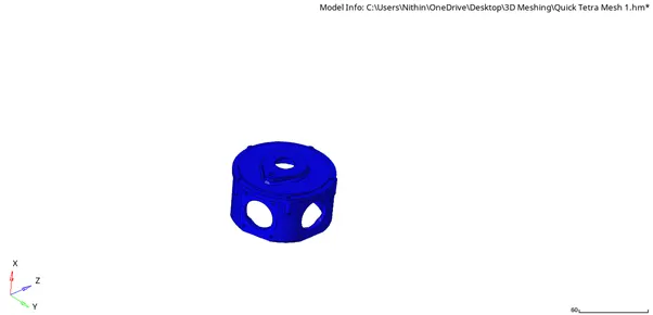
Chasis : This model was meshed the third method.
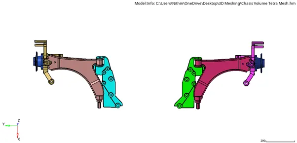
Step 1 : Import the model into the hypermesh window.
Step 2 : The components are meshed separately for this model.
Step 3 : Select “Volume Tetra” from the 3D tetra mesh panel.
Step 4 : Keeping solids select “solids” from the drop down of to mesh the model.
Step 5 : Check in for “Use Curvature” and “Use proximity” for the components. Also check in for clean up option.
Step 6 : Enter the target element size.
Note : For this method there is no minimum or maximum length that needs to checked in quality criteria. Only the Tet Collapse should be checked for the given value.
Step 7 : Click on mesh to perform 3D tetra mesh for the components.
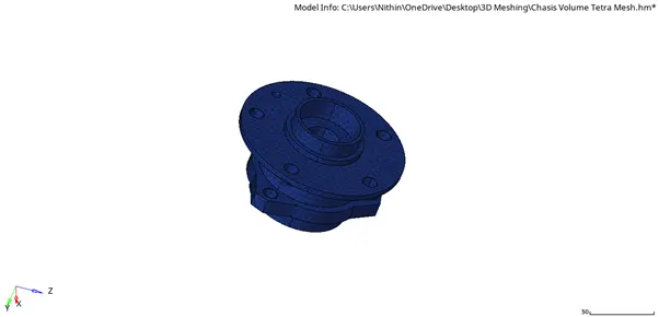
Note : The above component was meshed using the first method that is “Conversion of 2D tria elements into 3D tetra elements” .
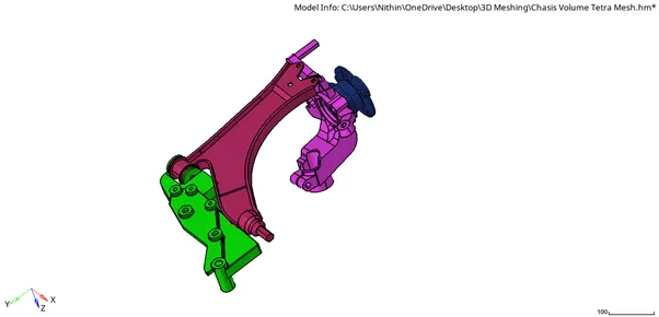
Note : The meshing of these components were not reflected to the other side cause the total number of elements were exceeding the limit.
To resolve the tet collapse of the models there three methods.
1 ) By altering the distance of the side which has the highest length by dividing it by 1.4 (this method is used only when there are very few tet collapse elements).
2 ) By using “translate” option from the tools panel.
3 ) By using “Tetra re-mesh” option from the 3D tetra mesh panel. In this the tetra mesh parameter option is used and in that the specifications for the mesh and tet collapse are entered.

As the above picture represents.
Result : The models and its components were meshed successfully to 3D mesh for the given quality criteria.