Week 8 Challenge
CHALLENGE 7
Aim: The main aim of this challenge is to gain the knowledge about the concept of application of the loads to the structure with the help of a STAAD software. The concept of applying the load combination with the help of the software is also learnt. The procedure that is adopted to assign the member properties to the members is also learnt. And the concept of determining the errors and fixing up the warnings are also learnt.
Loading, Analysis and Design Procedure in STAAD Pro
- Applying Load Exercise
For the structure modelled in previous exercise. Apply following loads
- Form a Load case as DL for Dead Load
- Apply Self weight
- Apply member load of 3 kN/m on the rafter
- Apply member load of 6 kN/m on the secondary beams
- Apply point load of 20 kN at node intersecting inclined member on the top chord.
- Form a Load case as LL for Live Load
- Apply member load of 4 kN/m on the rafter
- Apply member load of 7.5 kN/m on the secondary beams
- Form load combination 1.5DL+1.5LL
Ans:
- In order to define the loads go to the loading option under geometry and select the load case option and define the loading types as dead load and live load. Name dead load types as DL and live load type as LL
- Now select DL and click on the add button to add that comes under DL. As per the given question the DL are 3kN/m for rafter, 6kN/m for secondary beams and a point load of 20kN at the intersection of the inclined members of the rafter.
- For 3kN/m and 6kN/m select the command as uniform force and for 20kN select the command as nodal force.
- Click on the load to be assigned and then select the member for which the particular load as to be assigned and the select the assign to the selected beams or nodes.
- In order to define the load combination select the command option and under command option select loading, under loading there is a option called load combination select that. Then the dialogue box appears with the load that we have defined. Select DL and LL and give the factor as 1.5 for both DL and LL. Save the combination with appropriate name.
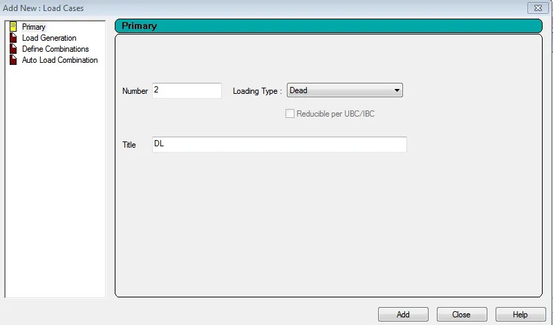
- DEFINING OF DEAD LOAD(DL)
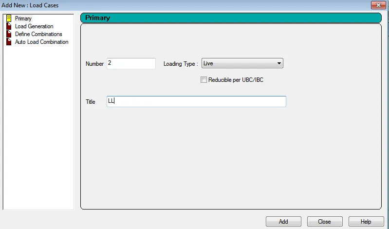
- DEFINING OF LIVE LOAD(LL)
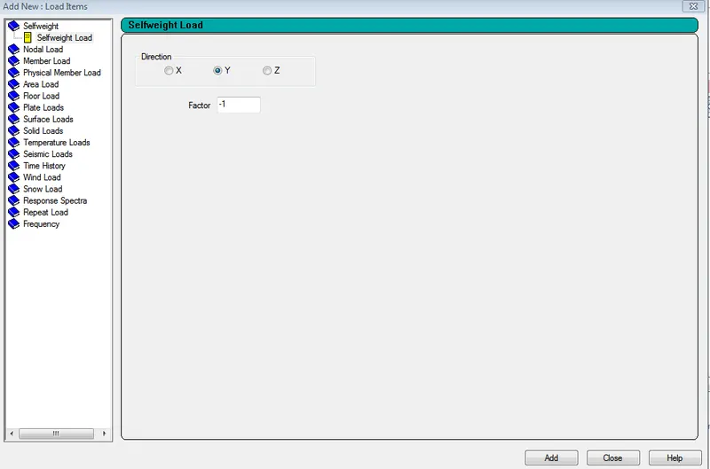
- DEFINING OF SELFWEIGHT
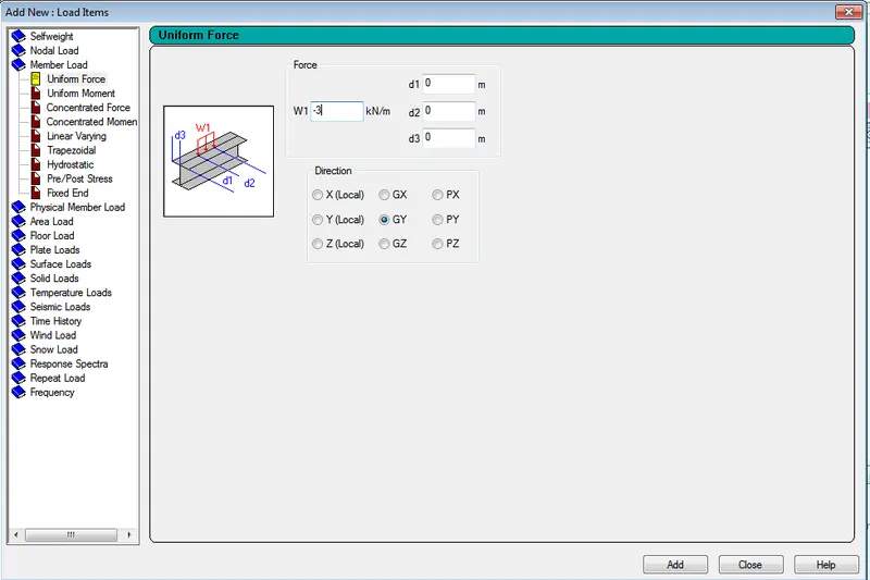
- DEFINING OF 3kN/m FOR DL ON THE RAFTER
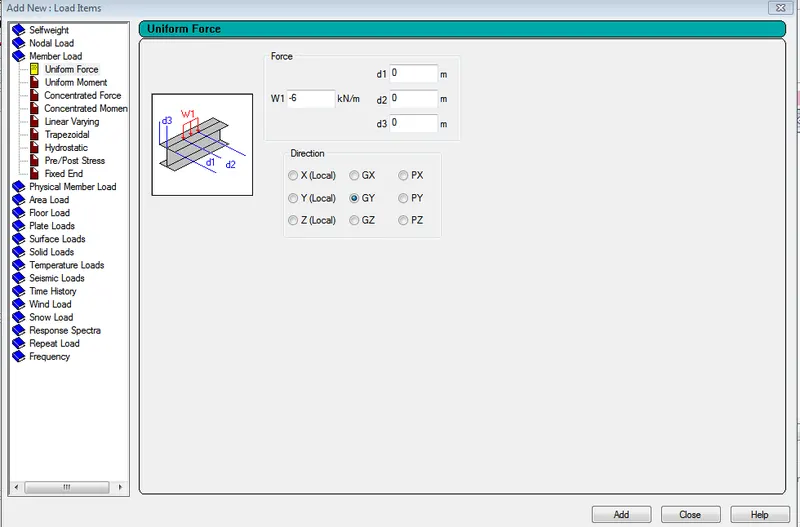
- DEFINING OF 6kN/m FOR DL ON THE SECONDARY BEAMS
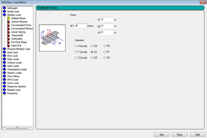
- DEFINING OF 4kN/m FOR LL ON THE RAFTER
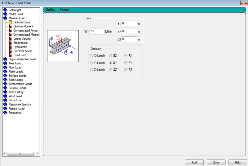
- DEFINING OF 7.5kN/m FOR LL ON THE SECONDARY BEAMS
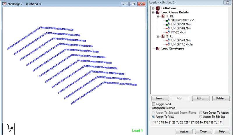
- ASSIGINING OF 3kN/m TO THE RAFTER
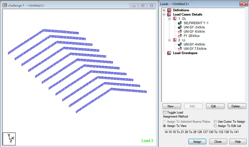
- ASSIGINING OF 4kN/m TO THE RAFTER
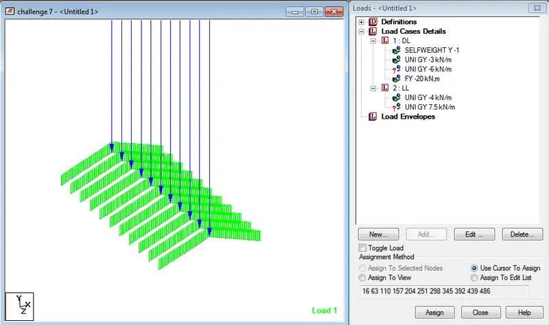
- ASSIGINIGN OF 20kN AT THE JOINT OF THE RAFTER
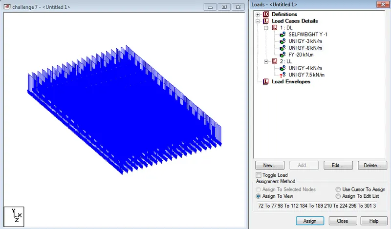
- ASSIGINING OF 6kN/m TO THE SECONDARY BEAMS
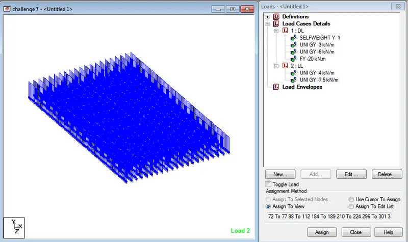
- ASSIGINING OF 7.5kN/m TO THE SECONDARY BEAMS
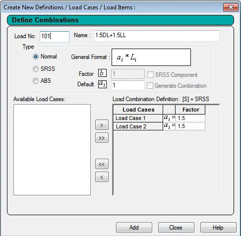
- DEFINING OF LOAD COMBINATIONS
- Find Maximum Force and Minimum Force for member and present the STAAD result.
- Continue previous challenge, Run the analysis and find following results on the member mentioned
- Run the analysis
- Find the Maximum Moment in the Secondary beam for 1.5DL+1.5LL case
- Find the Maximum Axial force on the inclined bracing and identify the member having the maximum force for 1.5DL+1.5LL case
- Identify Bottom chord of Truss having Maximum shear Force & Maximum moment for 1.5DL+1.5LL case and present the values.
Ans:
- The maximum moment in the secondary beans for load combination1.5DL+1.5LL is 53.099kN-m
- The maximum axial force on the inclined bracing member for 1.5DL+1.5LL is 103.22kN and the maximum axial force occurred in the member having beam number 1055.
- The maximum shear force and the maximum bending moment at the bottom chord of the truss for 1.5DL+1.5LL are 257.82kN and 413.66kNm for the beam number 1087 and 78 respectively.
- View and Rectify the Warning, instabilities in the structure
For the attached STAAD file identify the Warnings and fix the same and run the analysis
Ans:
- In order to fix the errors in the given file first run the file as it is given. Then identify the errors that is displayed in the output file.
- Then come to the modelling file and then select the command option and select the analysis option. In the analysis option select the perform analysis option. With this the errors will be sorted off.
- To set up the warning, the warnings that comes after running the file are instability of the joint at the node 47 and 48. In order to fix the warnings select the particular nodes and assign the members and truss property to it then run the analysis. With this the warnings are also fixed.
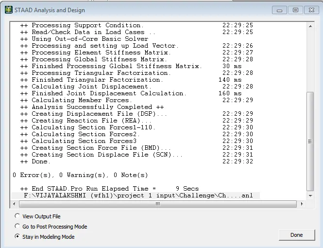
- FIXING OF ERRORS AND THE WRNINGS FOR THE GVEN MODEL
- Design Parameter exercise
- In continuation to challenge 1, Apply Design parameter for structure modelled for code IS800:2007.
- Effective Length Lx, Ly, Lz for beams, Truss elements
- Effective length factors Ky, Kz for Columns
- Apply other design parameters for respective members
Ans:
- For assigning the design parameter for the steel structure select code as IS800 – 2007 – LSD command in the code selection drop list.
- Then define the yield strength and the ultimate tensile strength value for the steel that is used for the structure i.e FU and FYLD command for design.
- Then provide appropriate KX, KY, KZ and LX, LY,LZ values for the columns as per the slenderness condition.
- Select the main as 180 for columns
- Select ratio as 1 for the entire structure
- Select beam as 1 for the structure.
- In the same way apply other parameters that are suitable for the analysis and design of the structure.
- At the final select the check for the code and steel take off command
- Then run the file and check for the errors and warnings and if any errors or warnings, fix them.
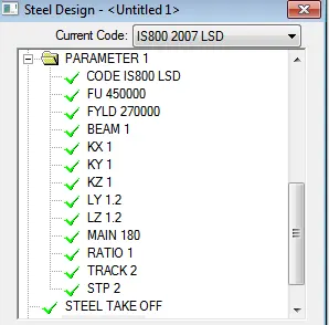
- DEFINING OF DESIGN PARAMETERS
Conclusion:
From the project carried out it can be concluded that the concept of the application of the loads and defining of the load combination to the structure as per the given data with the use of the STAAD software is learnt. The procedure that is followed while assigning the loads to a structure is known. The method that as to be adopted for fixing up the errors and the warning are also learnt. The design parameters for the steel structures are also learnt.
Vijayalakshmi S H