Analysis & Design of a Piperack for Wind forces
CHALLENGE 14
Aim: The main aim of this project is to gain the knowledge about the concept of modelling of a pipe rack and the various levels that are considered during the modelling of a pipe rack. The concept of different platforms that are generally provided in the pipe rack are also understood.
Introduction: Pipe racks are elevated steel or concrete structures designed to support pipes, electrical and instrument cable trays. Sometimes it supports mechanical equipment, vessels, and valve access platforms also. The pipe rack supports all main process lines that connect equipment such as pumps, storage tanks, static vessels, and columns. It also connects various relief and blow down headers. All lines leaving and entering the plant, utility supplying lines such as steam, air, cooling water, inert gas, etc., are routed through a pipeline corridor.
Concept of pipe rack:
Pipe networks are considered as main components of industrial complexes like refineries and petrochemicals that transfer fluid and gas. Pipe rack is concrete or steel structure (better fire resistant) which carries multiple pipes carrying liquid or gas in different tiers and also carries Electrical/Instrument/Telecom Cable trays for supporting auxiliary Equipment like Pressure release valves etc. with walkways and service platforms. Structural steel pipe racks support pipes, power cables and instrument cable trays. They also carry large diameter to small bore lines with liquid or gas from one Equipment to another Equipment or from one unit to another unit. These are necessary for carrying large number of Process lines, Utility lines, Flare lines etc. Pipe racks have a series of transverse bents which run along the length.
These are spaced at uniform intervals of the pipe system around 20 ft. The transverse bents are typically moment frames and connected with longitudinal struts for maintenance access. Different types of pipes are used in the pipe rack. Utility pipes include steam, cooling water, fuel oil, extinguishing water, etc. They are mostly located in the middle of a one-level pipe rack or on the top level. Also there are the Process pipes. Process pipes carry product which is a part of chemical reactions. When there are multiple pipes, process pipes are heavy weighted or placed on the bottom level, they are placed outside of the utility pipes. At last there are relief pipes and flare pipes that fulfil a safety goal. They are always located on the outside of the rack to protect the installation against too much pressure. A complete structure of pipe rack system and its structural elements should perform their function adequately and safely, with appropriate degree of reliability during design life. It should be constructed before it becomes obstruction for other structures.
LOADING:
The different types of loads that are to be considered while designing the pipe racks are as follows:
- Dead load
- Live load
- Friction load
- Anchor load
- Wind load
- Earthquake load
- Thermal load
Dead Loads (D): The PIP Structural Design Criteria prescribes specific dead loads for pipe racks. Pipe racks and their foundations should be designed to support these loads applied on all available rack space, unless other criteria is provided by the client.
Structure dead load (Ds): The weight of materials forming the structure and all permanently attached appurtenances. This includes the weight of fire protection material, but does not include the weight of piping, cable trays, process equipment and vessels.
Operating dead load (Do): The operating dead load is the weight of piping, piping insulation, cable tray, process equipment and vessels plus their contents (fluid load). The piping and cable tray loads may be based on actual loads or approximated by using uniform loads.
Empty dead load (De): The empty weight of piping, piping insulation, cable tray, process equipment and vessels. When using approximate uniform loads, 60% of the operating dead load for piping levels is typically used. Engineering judgment should be used for cable tray levels.
Test dead load (Dt): The empty weight of the pipes plus the weight of the test medium.
Live load: Live load is one of the gravity load imposed by liquid or viscous materials in pipes during the operation along with which the human load is also added to it. Live load is defines as the load which is produced by the use and the occupancy of the structure thus not including any kind of construction or the environmental loads. Live load generally comes around the platform area, staircase and at the places where the access for the maintenance is provided.
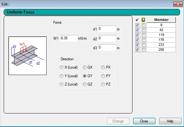
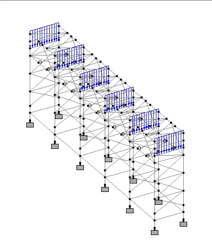
Friction load: Friction forces caused by hot lines sliding across the pipe support during startup and shutdown are assumed to be partially resisted through friction by nearby cold lines. Therefore, in order to provide for a nominal unbalance of friction forces acting on a pipe support, a resultant longitudinal friction force equal to 7.5% of the total pipe weight or 30% of any one or more lines known to act simultaneously in the same direction, whichever is larger, is assumed for pipe rack design. Friction between piping and supporting steel should not be relied upon to resist wind or seismic loads.
Anchor Loads: Pipe racks should be checked for anchor and guide loads as determined by the Pipe Stress Group. It may be necessary to use horizontal bracing if large anchor forces are encountered. For conventional pipe rack systems, it is normally preferred to either have the anchors staggered along the pipe rack so that each support has only one or two anchors, or to anchor most pipes on one braced support. For initial design, when anchor and guide loads are not known, use a longitudinal anchor force of 5.0 kN acting at mid span of each bent transverse beam (refer project design criteria). Guide loads are usually small and may be ignored until they are defined by the Pipe Stress Engineer. For non-continuous pipe rack systems, piping may be transversely guided or anchored at both cantilever frames and anchor bays. Longitudinal anchors may be located only at anchor bays.
Thermal Loads (T): The PIP Structural Design Criteria prescribes specific thermal loads for pipe racks:
- Thermal forces (T): The self-straining thermal forces caused by the restrained expansion of the pipe rack structural members.
- Pipe anchor and guide forces (Af): Pipe anchors and guides restrain the pipe from moving in one or more directions and cause expansion movement to occur at desired locations in a piping system. Anchor and guide loads are determined from a stress analysis of an individual pipe. Beams, struts, columns, braced anchor frames and foundations must be designed to resist actual pipe anchor and guide loads.
- Pipe friction forces (Ff): These are friction forces on the pipe rack structural members caused by the sliding of pipes in response to thermal expansion due to the design (operating) temperature of the pipe. For friction loads on individual structural members, use the larger of 10% of the total piping weight or 40% of the weight of the largest pipe undergoing thermal movement: 10% of the total piping weight assumes that the thermal movements on the individual pipes do not occur simultaneously; 40% of the largest pipe weight assumes steel-on-steel friction.
Wind Load: Transverse wind load on structural members, piping, electrical trays, equipment, platforms, and ladders should be determined in accordance with project approved design code. Longitudinal wind should typically be applied to structural framing, cable tray vertical drop (if any), large dia pipes vertical drop (if any) and equipment only. The effects of longitudinal wind on piping and trays running parallel to the wind direction should be neglected.
Earthquake Loads: Earthquake loads in the vertical, transverse, and longitudinal directions should be determined in accordance with the project design criteria. Vertical, transverse, and longitudinal seismic forces generated by the pipes, raceways, supported equipment, and the pipe rack structure should be considered and should be based on their operating weights. Pipes must be evaluated for seismic loads under both full and empty conditions and then combined with the corresponding gravity loads.
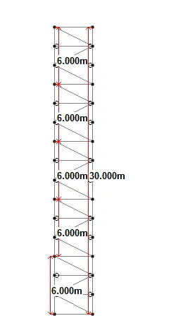
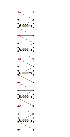
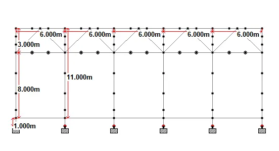
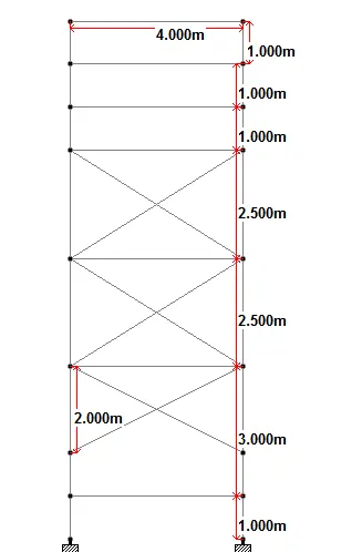
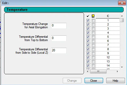
- Model a pipe rack in staad pro as per given parameters, Total length of pipe rack is 30m which is straight in shape, centre to centre distance between columns is 6m.Pipe rack is of 4 level (with one additional empty level),Total height of pipe rack is 11m (from top of the pedestal to top of the pipe rack),Take height of pedestal 1m,Geometry of pedestal is required, and Width of pipe rack is 4m which is single bay, Use ISMB and angle sections. For the given geometry apply the loads as follows, Take DL for piping level 2.5kN/m2,Take DL for cable trays 0.5kN/m2,Total equipment load 1kN,Live load 5kN/m2, Take 10% friction load, Design structure for the temperature load of 20.Location of project is Chennai.
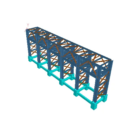
Ans: The pipe rack is of 30m in total length which is of straight in shape. The total height of the pipe rack is taken as 11m from the top of the pedestal to the top of the pipe rack with 1m height of pedestal. The pipe rack has only four levels with one additional level. The columns are spaced at a distance of 6m c/c.
PLAN OF THE PIPE RACK AT 8m HEIGHT FROM THE TOP OF THE PEDESTAL
PLAN OF PIPE RACK AT 11m HEIGHT FROM THE TOP OF THE PEDESTAL
ELEVATION OF PIPE RACK FROM EAST DIRECTION
SECTION VIEW OF PIPE RACK
3D VIEW OF MODEL
DEFINITION OF LOADS
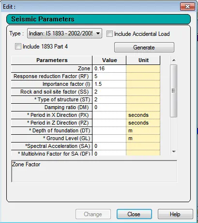
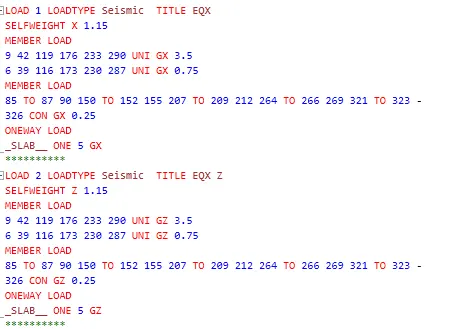
EARTHQUAKE LOAD DEFINITION
DEAD LOAD
PIPING LOAD
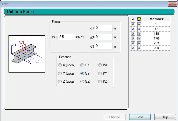
EQUIPMENT LOAD
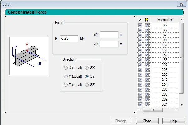
CABLE TRAY LOAD
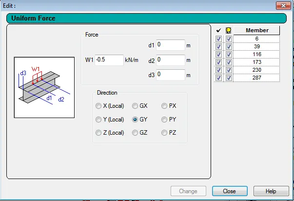
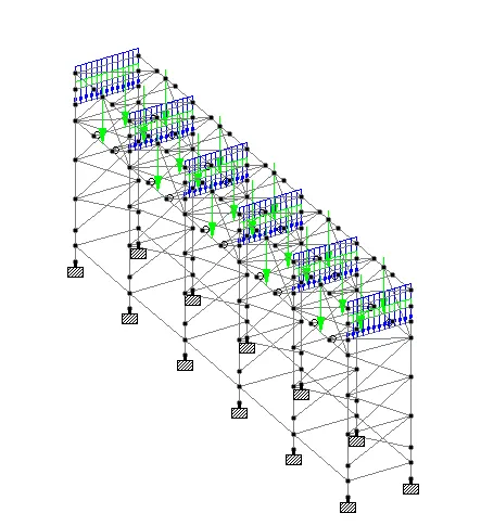
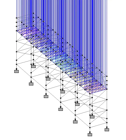
LIVE LOAD
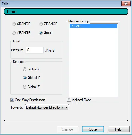
FRICTION LOAD
TEMPERATURE LOAD
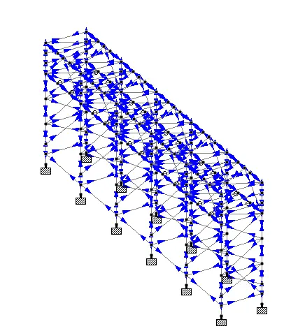
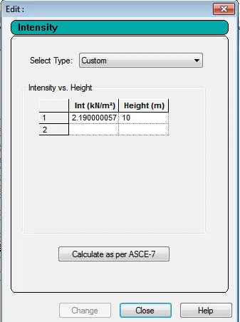
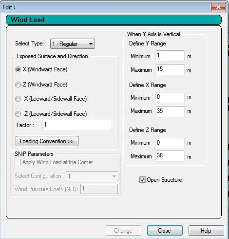
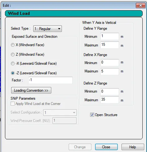
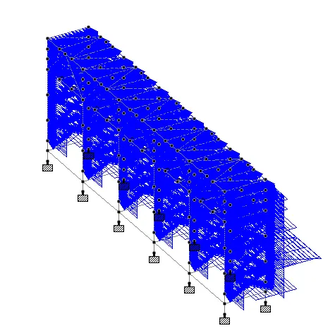
WIND LOAD DEFINITATION
WIND LOAD ALONG +X DIRECTION
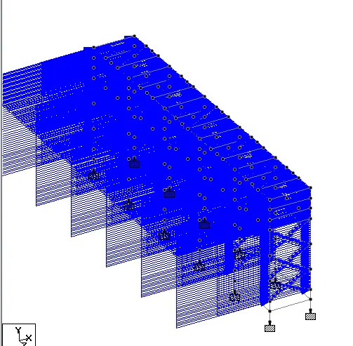
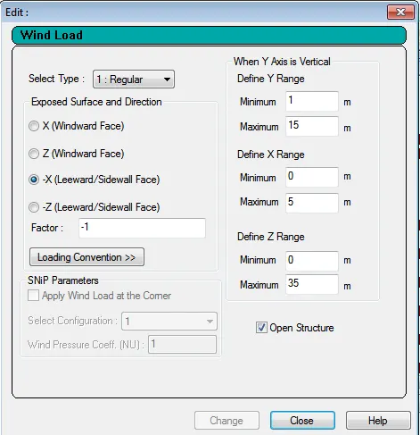
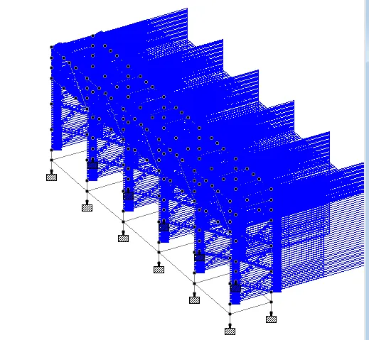
WIND LOAD ALONG -X DIRECTION
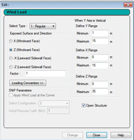
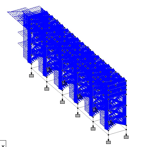
WIND LOAD ALONG +Z DIRECTION
WIND LOAD ALONG -Z DIRECTION
LOAD COMBINATIONS:
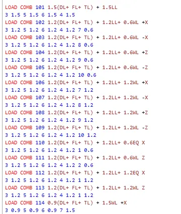
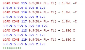
THE LOAD COMBINATIONS AS PER THE IS CODECONSIDERED ARE AS FOLLOWS
- 1.5 (DL+FL+ FL)+ 1.5LL
- 1.2 (DL+FL+TL) +1.2LL+0.6WL+X
- 1.2 (DL+FL+TL) +1.2LL+0.6WL-X
- 1.2 (DL+FL+TL) +1.2LL+0.6WL+Z
- 1.2 (DL+FL+TL) +1.2LL+0.6WL-Z
- 1.2 (DL+FL+TL) +1.2LL+1.2WL+X
- 1.2 (DL+FL+TL) +1.2LL+1.2WL-X
- 1.2 (DL+FL+TL) +1.2LL+1.2WL+Z
- 1.2 (DL+FL+TL) +1.2LL+1.2WL-Z
- 1.2 (DL+FL+TL) +1.2LL+0.6EQX
- 1.2 (DL+FL+TL) +1.2LL+0.6EQZ
- 1.2 (DL+FL+TL) +1.2LL+1.2EQX
- 1.2 (DL+FL+TL) +1.2LL+1.2EQZ
- 0.9 (DL+FL+TL) +1.5WL+X
- 0.9 (DL+FL+TL) +1.5WL-X
- 0.9 (DL+FL+TL) +1.5WL+Z
- 0.9 (DL+FL+TL) +1.5WL-Z
Conclusion:
From the project carried out it can be concluded that the concept of modelling of a pipe rack with the use of the staad pro is understood. The concept of various levels that are to be taken into consideration while modelling of a pipe rack are understood. The concept of different platforms that are generally provided in the pipe rack are also understood.
Vijayalakshmi S H