Analysis & Design a Piperack for the provided specifications
CHALLENGE 7
Aim: The main aim of this project is to gain the knowledge about the concept of modelling of a pipe rack and the various levels that are considered during the modelling of a pipe rack. The concept of different platforms that are generally provided in the pipe rack are also understood.
Introduction: Pipe racks are elevated steel or concrete structures designed to support pipes, electrical and instrument cable trays. Sometimes it supports mechanical equipment, vessels, and valve access platforms also. The pipe rack supports all main process lines that connect equipment such as pumps, storage tanks, static vessels, and columns. It also connects various relief and blow down headers. All lines leaving and entering the plant, utility supplying lines such as steam, air, cooling water, inert gas, etc., are routed through a pipeline corridor.
Concept of pipe rack:
Pipe networks are considered as main components of industrial complexes like refineries and petrochemicals that transfer fluid and gas. Pipe rack is concrete or steel structure (better fire resistant) which carries multiple pipes carrying liquid or gas in different tiers and also carries Electrical/Instrument/Telecom Cable trays for supporting auxiliary Equipment like Pressure release valves etc. with walkways and service platforms. Structural steel pipe racks support pipes, power cables and instrument cable trays. They also carry large diameter to small bore lines with liquid or gas from one Equipment to another Equipment or from one unit to another unit. These are necessary for carrying large number of Process lines, Utility lines, Flare lines etc. Pipe racks have a series of transverse bents which run along the length.
These are spaced at uniform intervals of the pipe system around 20 ft. The transverse bents are typically moment frames and connected with longitudinal struts for maintenance access. Different types of pipes are used in the pipe rack. Utility pipes include steam, cooling water, fuel oil, extinguishing water, etc. They are mostly located in the middle of a one-level pipe rack or on the top level. Also there are the Process pipes. Process pipes carry product which is a part of chemical reactions. When there are multiple pipes, process pipes are heavy weighted or placed on the bottom level, they are placed outside of the utility pipes. At last there are relief pipes and flare pipes that fulfil a safety goal. They are always located on the outside of the rack to protect the installation against too much pressure. A complete structure of pipe rack system and its structural elements should perform their function adequately and safely, with appropriate degree of reliability during design life. It should be constructed before it becomes obstruction for other structures.
- Model a pipe rack in staad pro as per given parameters
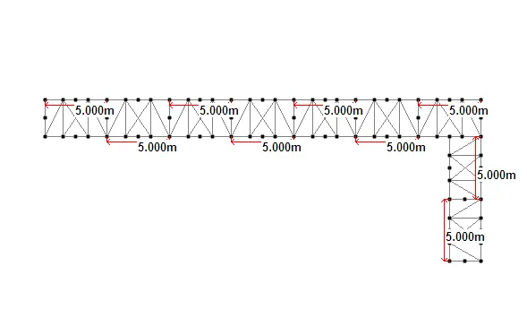
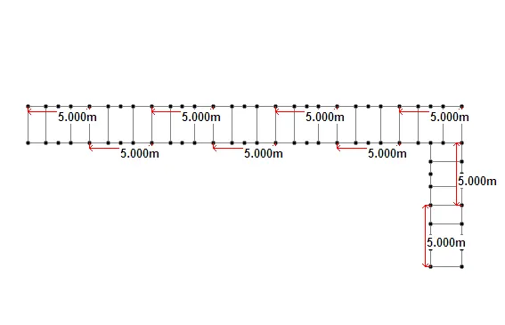
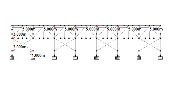
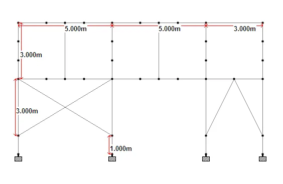
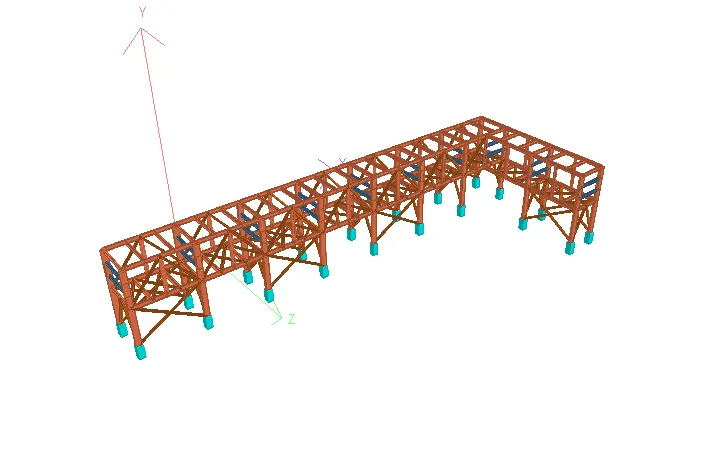
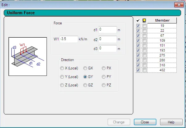
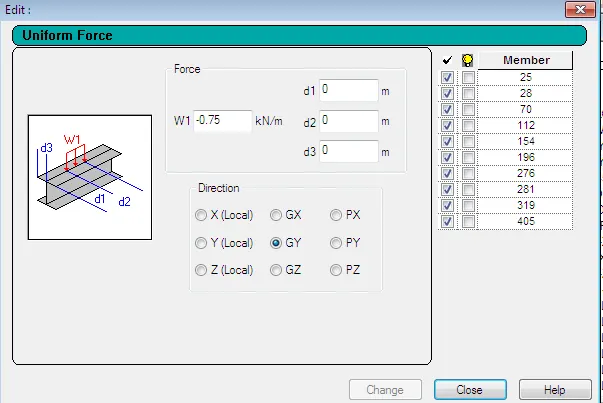
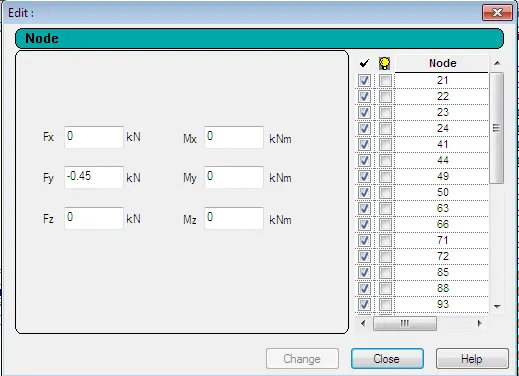
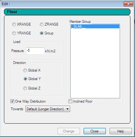
Total length of pipe rack is 45m which is L in shape, centre to centre distance between columns is 5m. Pipe rack is of 4 level (with one additional empty level), Total height of pipe rack is 6m (from top of the pedestal to top of the pipe rack), Geometry of pedestal is not required, Width of pipe rack is 3m which is single bay, Use ISMC and angle sections. For the given geometry apply the loads as follows, Take DL for piping level 3.5kN/m2, Take DL for cable trays 0.75kN/m2, Total equipment load 1.8kN, Live load 5kN/m2, Take 10% friction load, Design structure for the temperature load of 25. Location of project is Ahmedabad.
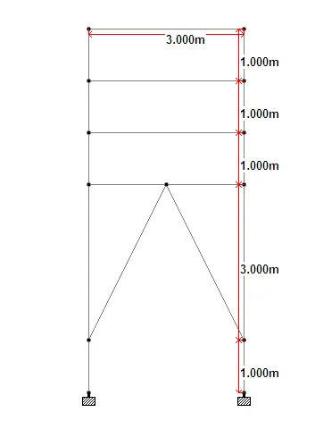
Ans: The pipe rack is of 45m in total length which is of L in shape. The total height of the pipe rack is taken as 6m with 1m height of pedestal. The piping line and the cable trays are spaced at a distance of 1m. The columns are spaced at a distance of 5m c/c.
PLAN OF THE PIPE RACK AT 3m HEIGHT FROM THE TOP OF THE PEDESTAL
PLAN OF PIPE RACK AT 6m HEIGHT FROM THE TOP OF THE PEDESTAL
ELEVATION OF PIPE RACK FROM SOUTH DIRECTION
ELEVATION OF PIPE RACK FROM EAST SIDE
SECTION VIEW OF PIPE RACK
3D VIEW OF MODEL
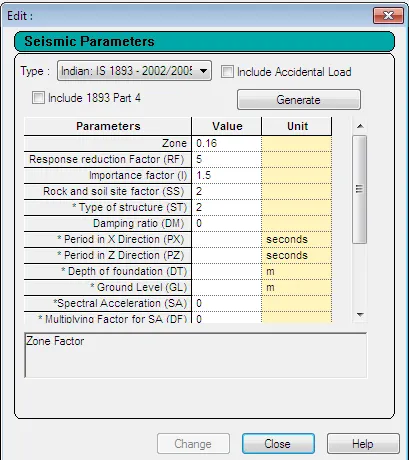
DEFINING OF EARTHQUAKE
Earthquake parameters
Ahmedabad is located in zone III and the zone factor is 0.16
Importance factor = 1.5
Reduction factor = 5
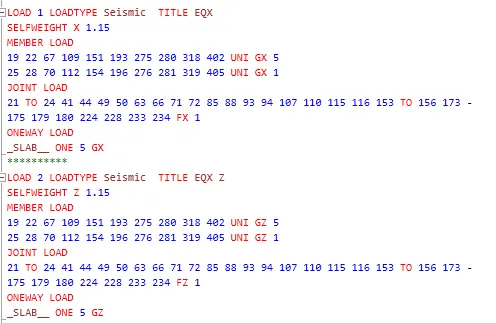
DEFINING OF DEAD LOAD
- DEAD LOAD ON PIPING LINE
- DEAD LOAD ON CABLE TRAYS
- DEAD LOAD OF EQUIPMENTS
DEFINING OF LIVE LOAD
- As per the IS code (IS 875 part 2) the live load for the industrial building it is considered as 5kN/m2
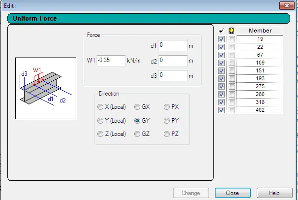
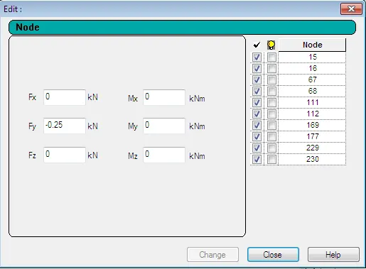
DEFINING OF FRICTION LOAD
- The friction load is taken as 10% of the dead load
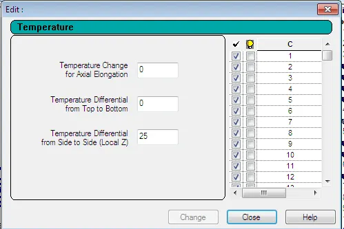
DEFINING OF TEMPERATURE LOAD
- As per the specification the temperature load is taken as 25
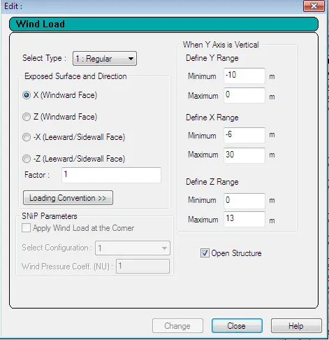
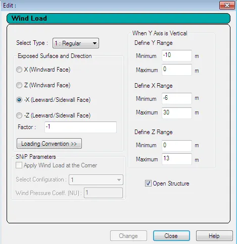
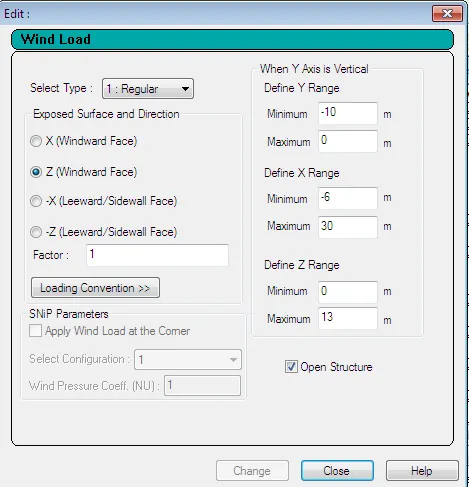
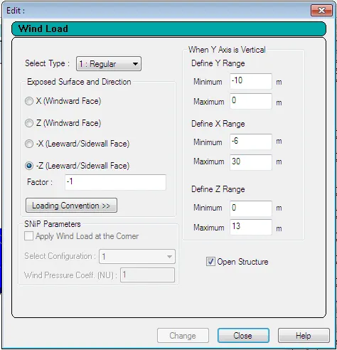
DEFINING OF WIND LOAD
- The wind load is calculated as follows:
The project is located in Ahmedabad thus the basic wind speed (Vb) is 39m/s
Total length of the pipe rack is 45m, width of pipe rack is 4m and the height of the pipe rack is 7m from the bottom of the pedestal.
Risk factor k1 = 1 (it is designed for 50 year life span of the structure) (from table 1 of IS 875 part 3)
The terrain category in this project is category 3. Therefore K2 for 7m height = 0.91(from table 2 of OS 875 part 3)
K3 the topography factor as per IS code is 1
K4, the cyclone factor = 1.15
Design wind speed (Vz) = Vb*k1*K2*k3*k4
= 39*1*0.91*1*1.15
= 40.8135m/s
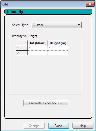
Design wind intensity (Pz) = 0.6*(Vz^2)
=0.6*40.8135^2
=999.44N/m^2 = 1kN/m^2
WIND LOAD AONG +X
WIND LOAD ALONG -X
WIND LOAD ALONG +Z
WIND LOAD ALONG -Z
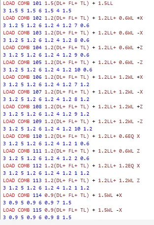
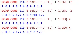
LOAD COMBINATIONS
THE LOAD COMBINATIONS AS PER THE IS CODECONSIDERED ARE AS FOLLOWS
- 5 (DL+FL+ FL)+ 1.5LL
- 2 (DL+FL+TL) +1.2LL+0.6WL+X
- 2 (DL+FL+TL) +1.2LL+0.6WL-X
- 2 (DL+FL+TL) +1.2LL+0.6WL+Z
- 2 (DL+FL+TL) +1.2LL+0.6WL-Z
- 2 (DL+FL+TL) +1.2LL+1.2WL+X
- 2 (DL+FL+TL) +1.2LL+1.2WL-X
- 2 (DL+FL+TL) +1.2LL+1.2WL+Z
- 2 (DL+FL+TL) +1.2LL+1.2WL-Z
- 2 (DL+FL+TL) +1.2LL+0.6EQX
- 2 (DL+FL+TL) +1.2LL+0.6EQZ
- 2 (DL+FL+TL) +1.2LL+1.2EQX
- 2 (DL+FL+TL) +1.2LL+1.2EQZ
- 9 (DL+FL+TL) +1.5WL+X
- 9 (DL+FL+TL) +1.5WL-X
- 9 (DL+FL+TL) +1.5WL+Z
- 9 (DL+FL+TL) +1.5WL-Z
Conclusion:
From the project carried out it can be concluded that the concept of modelling of a pipe rack with the use of the staad pro is understood. The concept of various levels that are to be taken into consideration while modelling of a pipe rack are understood. The concept of different platforms that are generally provided in the pipe rack are also understood.
Vijayalakshmi S H