Week 1 Challenge
CHALLENGE 1
Aim: The main aim of this challenge is to gain the knowledge about the concept of industrial structures and the properties of the materials that are used in the construction of the industrial building.
Introduction: Any building structure used by the industry to store raw materials or for manufacturing products of the industry is known as an industrial building. Industrial buildings may be categorized as Normal type industrial buildings and Special type industrial buildings. Normal types of industrial building are shed type buildings with simple roof structures on open frames. These buildings are used for workshop, warehouses etc. These building require large and clear areas unobstructed by the columns. The large floor area provides sufficient flexibility and facility for later change in the production layout without major building alterations. The industrial buildings are constructed with adequate headroom for the use of an overhead traveling crane. Special types of industrial buildings are steel mill buildings used for manufacture of heavy machines, production of power etc. The function of the industrial building dictates the degree of sophistication.
- Building configuration:
Typically the bays in industrial buildings have frames spanning the width direction. Several such frames are arranged at suitable spacing to get the required length. Depending upon the requirement, several bays may be constructed adjoining each other. The choice of structural configuration depends upon the span between the rows of columns, the head room or clearance required the nature of roofing material and type of lighting. If span is less, portal frames such as steel bents or gable frames can be used but if span is large then buildings with trusses are used.
The horizontal and vertical bracings, employed in single and multi-storey buildings, are also trusses used primarily to resist wind and other lateral loads. These bracings minimize the differential deflection between the different frames due to crane surge in industrial buildings. They also provide lateral support to columns in small and tall buildings, thus increasing the buckling strength.
- Floors:
Different types of floor are required in any factory from their use consideration such as production, workshop, stores, amenities, and administration. The service condition will vary widely in these areas, so different floors types are required. Industrial floors shall have sufficient resistance to abrasion, impact, acid action and temperatures depending on the type of activity carried out. High strength and high performance concretes can satisfy most of these requirements economically and is the most common material used. Foundation for vibrating machinery (such as reciprocating and high speed rotating machinery) should be placed upon rock or firm ground and it should be separated from adjacent floor to avoid vibrations.
- Roof System:
While planning a roof, designer should look for following quality lightness, strength, water proofness, insulation, fire resistance, cost, durability and low maintenance charges. Sheeting, purlin and supporting roof trusses supported on column provide common structural roof system for industrial buildings. The type of roof covering, its insulating value, acoustical properties, and the appearance from inner side, the weight and the maintenance are the various factors, which are given consideration while designing the roof system. Brittle sheeting such as asbestos, corrugated and trafford cement sheets or ductile sheeting such as galvanized iron corrugated or profiled sheets are used as the roof covering material. The deflection limits for purlins and truss depend on the type of sheeting. For brittle sheeting small deflection values are prescribed in the code.
- Truss type reasoning:
Out of the two through type truss systems shown below, which is the most efficient in carrying gravity load? Reason it out.
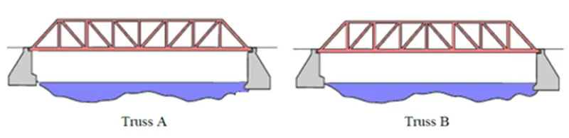
Ans: Truss A is Pratt truss type and Truss B is Howe truss type.
Pratt truss:
- A Pratt truss includes vertical members and diagonals that slope down towards the center, the opposite of the Howe truss.
- The interior diagonals are under tension under balanced loading and vertical elements under compression. If pure tension elements are used in the diagonals then crossing elements may be needed near the center to accept concentrated live loads as they traverse the span.
- It can be subdivided, creating Y- and K-shaped patterns.
- Also known as an ‘N’ truss, this form is often used in long-span buildings, with spans ranging from 20-100 m, where uplift loads may be predominant, such as in aircraft hangers.
- A Pratt truss uses vertical members for compression and horizontal members for tension. The configuration of the members means that longer diagonal members are only in tension for gravity load effects which allows them to be used more efficiently.
Howe truss:
- Howe trusses are essentially the opposite of Pratt trusses in terms of geometry. The entire structure is still relatively the same, but the diagonal braces are now occupying the opposite or the unoccupied joints. This switch in position of the diagonal members has a very important effect structurally.
- For Howe trusses, the reverse becomes true as diagonal members are now in compression, while the vertical loads are in tension. As they are similar in structure to Pratt trusses, their uses are generally the same.
- To maximize the efficiency of the truss, the truss can be loaded at the joints of the bottom chord. Roof trusses can be loaded with a ceiling load for example. Another thing to note is that, depending on the geometry and loading, Pratt trusses can have more unloaded members than Howe trusses.
- Thus truss A is more efficient in carrying the gravity load.
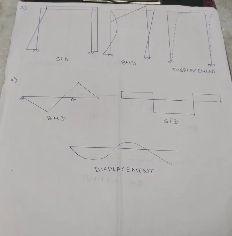
- Deflection shape & Bending Moment Drawing (Qualitative approach)
For the beam & Frame below draw deflected shape and bending moment drawing. (Qualitative approach). E & I are constants.
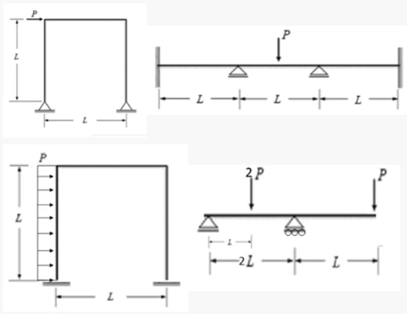
Ans: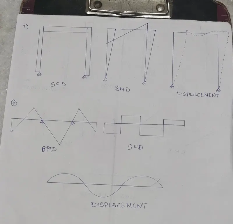
- Determine MOI, Weight, C/S area of sections below
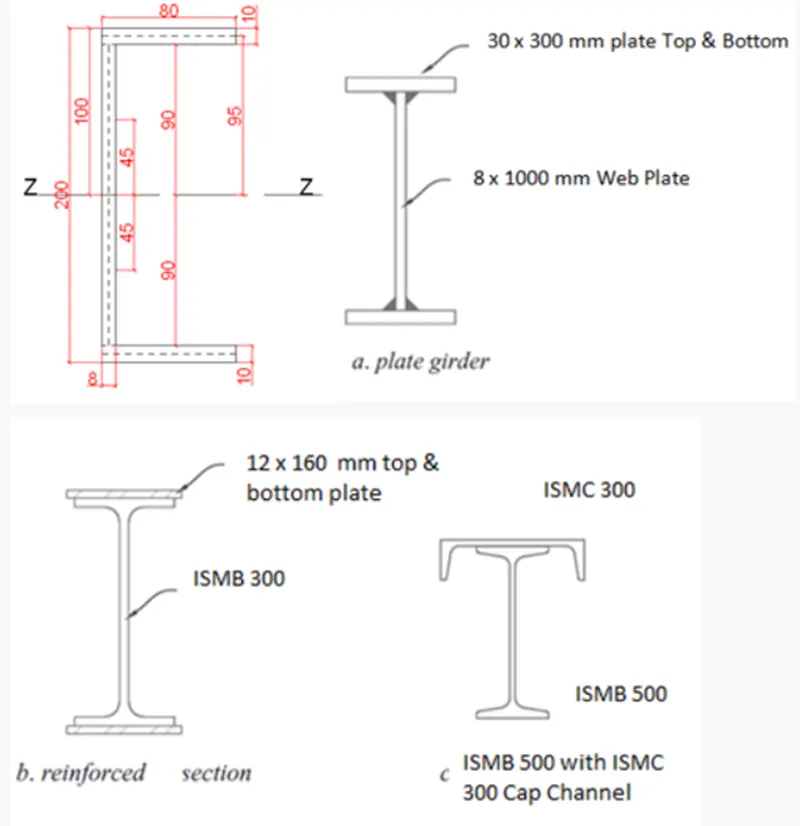
a) Moment of Inertia along X – axis
Ixx= (bh^3/12)-((b-tw) (h-2tf)^3)/12
b=80mm
h=200mm
tw=8mm
tf=10mm
=(80*200^3)/12 – ((80-8)(200-2*10)^3)/12
Ixx= 18.34*10^6 mm^4
Moment of Inertial along Y – axis
X = (A1X1+A2X2+A3X3)/ (A1+A2+A3)
A1=80*10 = 800mm^2
A2=180*8 = 1440mm^2
A3=80*10 = 800mm^2
X1=40mm
X2 = 4mm
X3=40mm
X= (800*40+1440*4+800*40)/ (800+1440+800)
X =22.94mm
H1 = 40-22.94 =17.06mm
Iyy1 = (10*80^3)/12+(800*17.06^2)
=659.5*10^3mm^4
H2 = 22.94 – 4 = 18.94mm
Iyy2 = (180*8^3)/12 + (1440*18.94^2)
=524.24*10^3mm^4
Iyy3 = (10*80^3)/12+(800*17.06^2)
=659.5*10^3mm^4
Iyy = Iyy1+Iyy2+Iyy3
= 659.5*10^3+524.24*10^3+659.5*10^3
Iyy= 1.8432*10^6mm^4
Area = 800+1440+800 =3040mm^2
Weight per meter= 23.84kg/m
b) Moment of Inertia along X – axis
Ixx = (a*h^3)/12 + (b/12) (H^3-h^3)
a=8mm
h=1000mm
b=300mm
H=1060mm
Ixx = (8*1000^3)/12 + (300/12) (1060^3 – 1000^3)
Ixx= 5442.06*10^6mm^4
Moment of Inertia along Y – axis
Iyy = Iyy1 + Iyy2 + Iyy3
Iyy1 = db^3/12
= (30*300^3)/12
= 67.5*10^6 mm^4
Iyy2 = d3^3/12
= 8^3*1000/12
= 42.667*10^6 mm^4
Iyy3 = db^3/12
= (30*300^3)/12
= 67.5*10^6mm^4
Iyy = 67.5*10^6+42.667*10^6+67.5*10^6
Iyy=135.04*10^6mm^4
Area = 26000mm^2
Weight per meter= 204.1 kg/m
c) Moment of Inertia along X – axis = 18540000 mrn4
Moment of Inertia along Y – axis = 1420000 mm4
Weight per meter= 74.34 kg/m
d) Moment of Inertia along X – axis = 64180000 mm4
Moment of Inertia along Y – axis = 81630000 mm4
Weight per meter= 74.34 kg/m
- Load calculation problem:
For the floor framing below, Calculate the load on interior beam, Exterior beam, Interior Girder and exterior girder having Floor Load of 10kN/m2
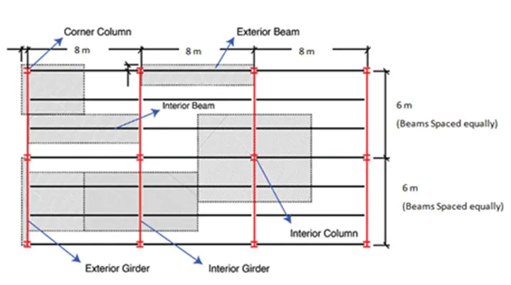
Ans: Floor load = 10kN/m2
Tributary width of exterior beam = 0.5(0+2) = 1m
Tributary width of interior beam = 0.5(2+2) = 2m
Tributary width of exterior girder = 0.5(0+8) = 4m
Tributary width of interior girder = 0.5(8+8) = 8m
Interior column = 49.04 KN
Corner column = 49.04/4 = 12.26 KN
Load on interior beam = 10*2 = 20 kN/m
Load on exterior beam = 10*1= 10 kN/m
Load on interior girder (for total 4 numbers interior girders) = 10*8 = 80kN/m
Load on interior girder (for total one number interior girders) = 20 kN/m
Load on exterior girder (for both exterior girders) = 10*4 = 40kN/m
Load on exterior girder (for one exterior girders) = 40/2 = 20kN/m
- Expansion joint size determination for temperature stated problem:
Assuming a bridge, made of steel, with an initial total length of 2000 m at -20 ºC, calculate the length difference at 40 ºC and its total length. Coefficient of Thermal expansion of steel = 12x10-6/°C
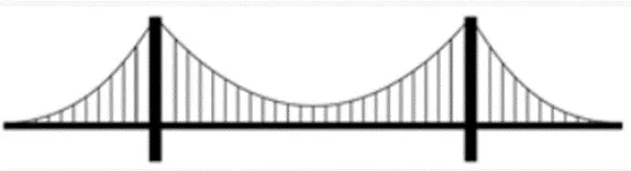
Ans: An initial total length of 2000 m at -20°C, Coefficient of Thermal expansion of steel = 12x10-6/°C
Length difference = 12x10-6/°C X 2000M X 40°C
Total length difference at 40°C is 0.96M
Conclusion:
From the project carried out it can be concluded that the various types of the industrial structures that are present are known and the different shapes of the sections that are used for the construction of the industrial building are known. The concept of calculating the moment of inertia and the load distribution pattern is also understood. The concept of bending moment, shear force and the deflection diagrams are also learnt from this challenge.
Vijayalakshmi S H