Week 8 - Challenge 4 - Coin Holder Design
AIM
Create the Coin Holder Plastic component through the given Class-A surface. To begin with, the tooling axis for the given Class-A Surface should be created meeting the requirements of the draft angle and at the end perform the Draft analysis on the model.
PROCEDURE
CREATING TOOLING AXIS
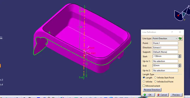
1 at first check the part model for possible way of creating tooling axis. Rotate the part in all directions and find out the most suitable direction for tooling direction. As Y directions seems to be the possible tooling direction
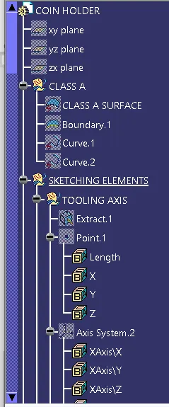
- Now extract the bin surface create a point on the surface and create the axis system using the point.
- now, using the created point and Y direction in the axis system create a line
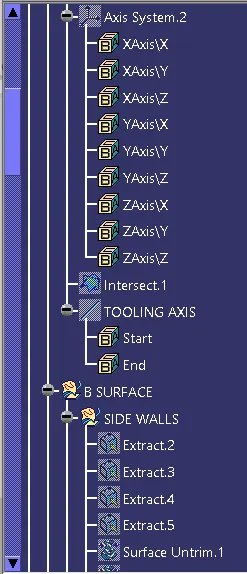
- this line can be considered as a tooling axis.
DRAFT ANALYSIS ON CLASS A SURFACE
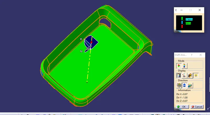
- At first change the view mode into material mode. Then the feature draft analysis is enabled.
- Go to insert – Analysis – feature draft analysis.
- The drag the compass and place it on the tooling axis and click on the model.
- The part model will be converted in to GREEN color. Some parts were remained in red, change the orientation of the compass so that the model turned into green.
CREATING B SURFACE
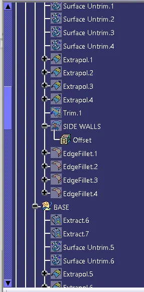
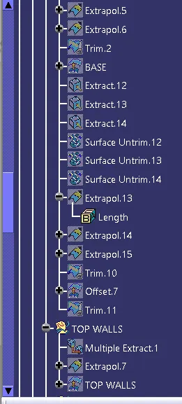
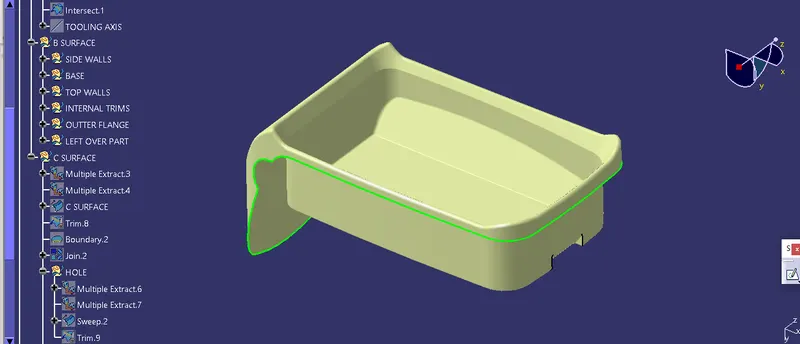
At first consider the class A surface, divide the part model into possible parts as base, side walls etc. now extract the each divided parts separately, then untrim the surfaces individually, then trim the surfaces into possible shape, then offset the surface with value of 2.5mm thickness. Repeat this process to every divided part in the model and give the fillets wherever it is required.
CREATING C SURFACE
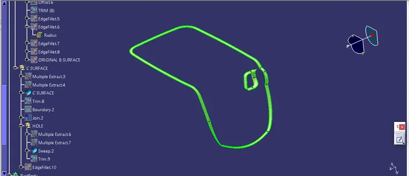
So take the class A surface, by using multiple extract command create the boundaries using edges of the class A surface, now using sweep command and using with reference to the surface option take the created boundary as a guide curve and reference surface as class A. then the c surface is created.
JOINING CLASS A AND CLASS B
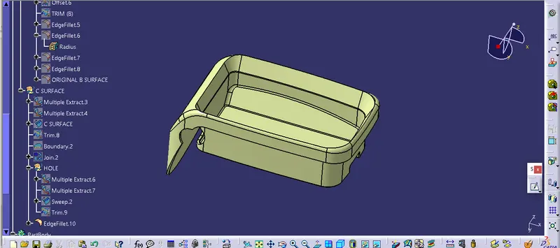
At first trim the C surface and B surface to get the proper surface to join the trimmed surface to the class A, so the trimmed surface is joined with class A to form closed body.
CREATING SOLID BODY
Now using part workbench define the work object as part body using closed surface command convert the closed body into solid body.

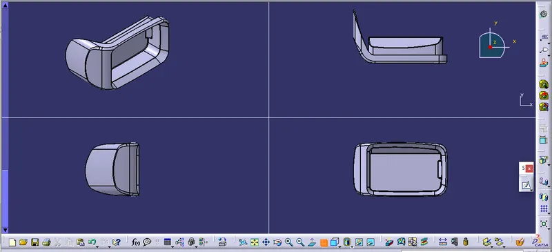
VIEWS:
ISOMETRIC VIEW, TOP VIEW, FRONT VIEW, SIDE VIEW
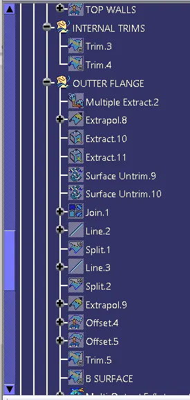
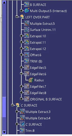
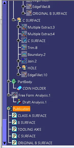
FEATURE TREE