Week 8 - Challenge 4 - Coin Holder Design
AIM: To Create the Coin Holder Plastic component through the given Class-A surface and to create the tooling axis for the given Class-A Surface meeting the requirements of the draft angle and at the end perform the Draft analysis on the model. The thickness of the component should be 2.5 mm.
OBJECTIVE
- Creating Tooling Axis
- Creating B and C Surface
- Performing Draft analysis in given Class-A surface and created plastic component
INTRODUCTION
CLASS A SURFACE
Class-A is a term used specifically in automotive design. It describes the final production surface data for the aesthetic parts of the car.
CLASS B SURFACE
The Class B finish is a quality finish with only minimal imperfections. A Class B finish is the most common finish for exterior surfaces. It is normally specified on surfaces such as external covers, panels, and parts that are fairly prominent.
CLASS C SURFACE
The Class C finish allows more imperfections than Class A or B. Class C is often specified for interior surfaces not readily visible, surfaces that will be covered by another part when assembled, or surfaces that the Customer feels do not need to meet a high cosmetic finish.
PROCEDURES
First, we joined all the parts using the join command to form a Class A from the Input geometrical set.
Draft Analysis
The draft analysis will help you quickly gather the draft angle on multiple surfaces without the need for tedious manual measurements. Here is a quick rundown of how the icon works when you have a given die direction.
First, we need to create a tooling axis for performing a Draft Analysis.
Basically, we need two bisecting lines in the X and Y Direction to create a tooling axis, but here don't need bisecting lines because the base of the coin holder is a flat surface. So we create tooling directly from the surface with respect to the point and Axis system.
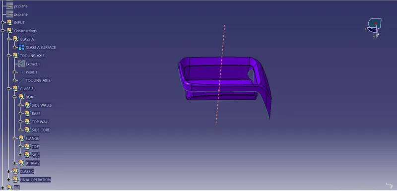
Here we generate a tooling axis from the base surface of the given component using the extract tool.
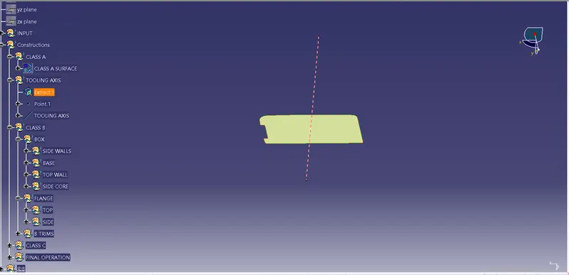
Now we go to insert< analysis< draft analysis and follow the usual procedure to do the analysis.
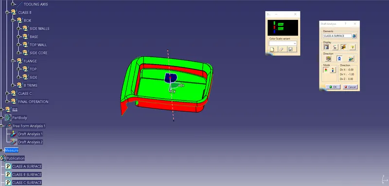
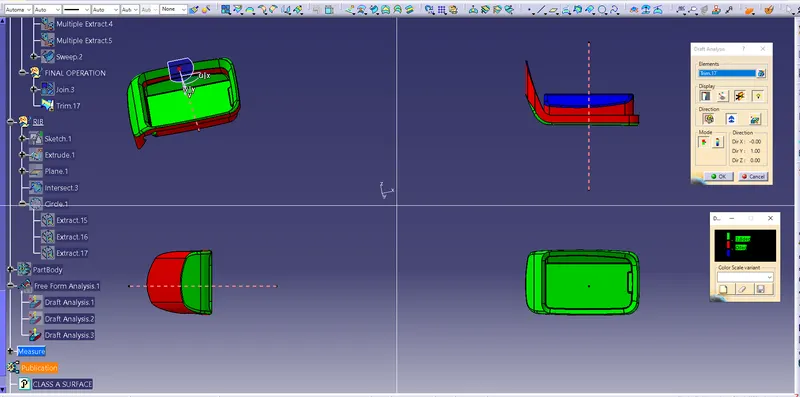
Align the compass and click on the surface and as expected the model is mostly in red colour i.e. negative draft with respect to the axis.
To correct it as best as we can we moved the compass a bit till we got most of the surfaces in green and locked that position.
After hitting ok, we change the direction of the line from the z-axis to the compass direction. The axis will align itself accordingly.
CREATING B SURFACE.
Now create the Plastic design for the given Class-A surface of the Center Console Coin Holder by creating the Class B and C surfaces.
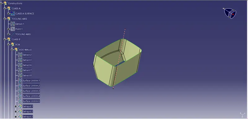
Create a Geometrical set in a tree and name it. Extract the sidewall surface of the Center Console Coin Holder by the Extract option by selecting the face. Select the faces.
Untrim the extracted surface using the Untrim option by selecting the surfaces.
Extrapolate the Untrimmed surfaces using the Extrapolate option. In Extrapolate Definition: Boundaries - select the edge of the Untrim surface and Extrapolate - untrimmed surface and offset the surfaces to 2.5mm in the opposite direction to the Class A surface
Extract the base surface and block and do the same process and offset the surface to a distance of 2.5mm in the downward direction.
Trim the Excess portion of the surfaces using the trim option.
Do the same process for inclined walls surface and outside wall surface by extracting and offsetting the surface and trimming the component.
Add the fillets to the wall's edges.
Next, extract the flange surface of the A surface which highlight in brown and yellow colour in A Surface and then use the Multiple extract options to extract the surfaces. Offset with 2.5 mm in the inner direction.
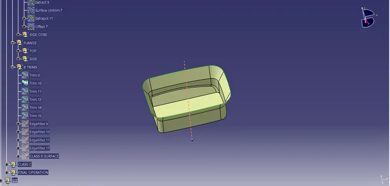
Extrapolate the edges for easy trimming and finally in the B surface trim all the faces which create the base, block and flanges.
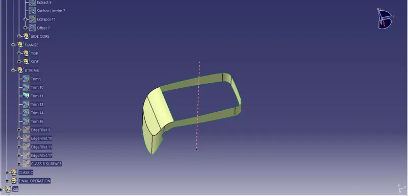
This is the B Surface which is created from A surface with given edge fillets in orders to A surface fillets.
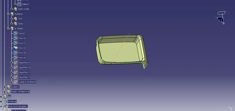
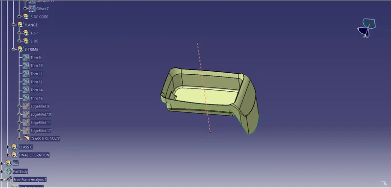
CREATING C SURFACE:
Create the class C surface for the class A surface by using the Multi extract option by selecting the boundaries. Create a smooth curve for the extracted boundary. Select the extracted boundary.
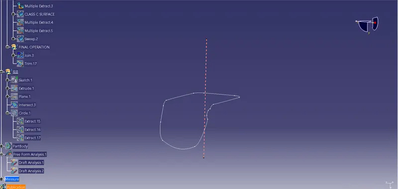
Extract the outer boundary walls and Replace the Multi extract boundary with a Smooth curve.
Now using the Sweep option create the C surface by selecting the Subtype as - with reference surface and Guide curve as - Boundary which is extracted and Reference surface as - Extracted boundary surface.
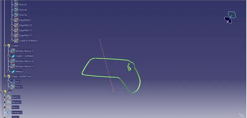
Join the surfaces with Class A and Class C using the Join tool option.

Check for any open boundaries in Plastic design and create the solid surface for the design in Part design using a closed surface option.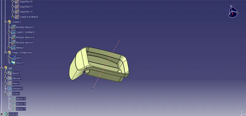
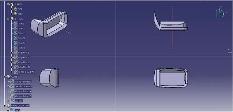
Isometric and Orthographic view of Plastic component
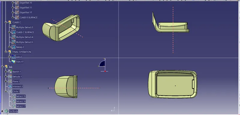
Now do the draft analysis for the solid component tooling axis and check for the draft angle as it should be in green in colour in the tooling axis.
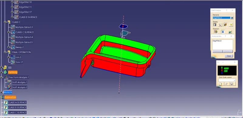
FINAL BODY
By using tool Close surface tool to change the part solid body.
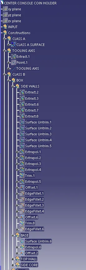
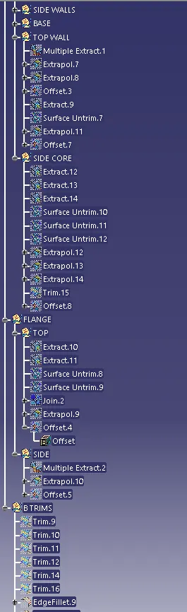
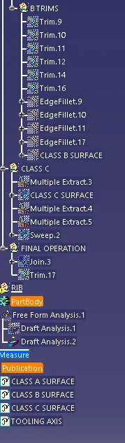
TREE STRUCTURES
CONCLUSION
Here, we created the Part component from the given Class-A Surface of Coin Holder Design and performed the draft analysis with respect to the tooling axis in the proper tree structures.